Sequence control of factory automation (FA) and foundation and ingenuity of ladder circuit
Many factory automation (FA: production factory) facilities use sequence control. The control device that controls that is called PLC (Programmable Logic Controller: commonly known as sequencer) is used, and many of them are described by ladder circuits (some language description is also included). I would like to explain sequence control and ladder circuit.
What is sequence control?
Sequence control is a control for performing sequence operation, “control that advances through each step of control with a predetermined order and exchange”.
“It is extremely used in production plants with control that moves all the way by faithfully observing a predetermined series of movements.”
Also, in production factories, there are many PLCs of the type to describe with ladder circuits which are relatively easy to describe because there are many cases where specification changes and control of control are required, as it is necessary to make facilities and movements peculiar to that production.
What is a ladder circuit?
As I mentioned earlier, factory automation (FA) is often required to change specifications and versatility.
Meanwhile, The ladder circuit is a kind of visual program that made it possible to program the program visually.
As an example, we will create a circuit by combining the following pictures to sequence operation.
However, detailed settings and functions of this visual also differ depending on PLC manufacturer.
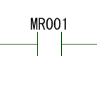
· A contact (ON when passing)
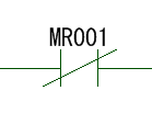
· B contact (OFF when passing through circuit)
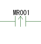
· Rising pulse contact (Pass only ON cycle)
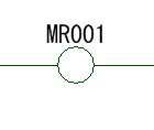
· Coil (ON when circuit is connected)
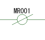
· NOT coil (OFF when the circuit is connected, ON if the circuit is not connected)
Before creating a ladder circuit
There are a couple of things you want to be aware of when creating ladder circuits, and we will explain it based on that because there are a lot of merits to describe ladder circuits.
Input and output
Basically, PLC is sequenced as input and output as relay as externally exchanged.
Therefore, each PLC has a hardware connection destination.
· Input: Sensor, switch, encoder, etc.
· Output: Valves, lamps, motors, etc.
In the ladder circuit, input and output are used with the ladder circuit name.
In this article
Input: R2000, R2001
Output: R50000, R50001
I will do that.
Other than that, MR001 etc. are used, but the internal switch (control inside the PLC).
These differ depending on the manufacturer of the PLC and the software of the ladder circuit.
Behavior of input and output is related to control of direct operation.
Although it is basic to make a program, please keep the simple part as much as possible as much as possible with the outside part.
It becomes easy to understand, and human error can be reduced.
How to use the input and output in the ladder circuit as simple as possible
Flow of operation of ladder circuit
Depending on PLC and creation software, recent trend is to have more than one program drawing describing ladder circuit.
You can change the order by setting, but we will execute the program according to that order. Also, we will execute the ladder circuit in the program drawing in order from the top.
The following is an example of a program drawing.
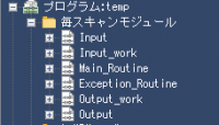
· Input: Program of receiving process from external input
· Input_work: Program of conversion from input
Main_Routine: Main control program
· Exception_Routine: Exception handling program
· Output_work: conversion program to output
Output: Processing program for external output
It was made.
In this case, in order from the top
“Input” → “Input processing” → “Main control” → “Exception control” → “Output processing” → “Output”
It has become.
Since it is flowing from input to control via control, if there is input, we will process immediately and go out. (Processing ends within one cycle)
If this order is ambiguous, it takes several cycles from control to output and takes time to output.
(The cycle depends on the PLC and the program amount, one cycle: several μs to several tens of ms)
In the order of “output processing” → “output” → “main control” → “exception control” → “input” → “input processing”
If there is input
“Input” → “Input process” “Main control” → “Exception control” “Output process” → “Output”
It will become.
described in the program drawing The ladder circuit runs from the top to the bottom of the program.
(When execution is completed to the bottom, it will run from the top of the next program drawing)
Therefore, let’s write from the top like ladder circuit description order like “input” → “control” → “output” .
The following is a program drawing, and a space describing a ladder circuit
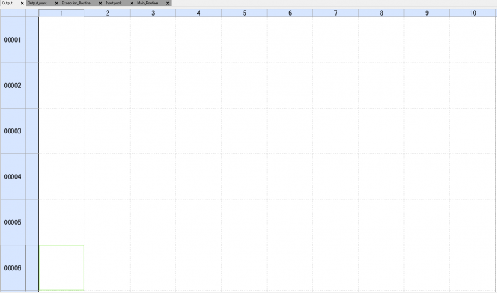
It is also possible to divide the scan cycle (program execution cycle) by program drawing unit.
By dividing it, it is possible to reduce the load on the control unit and to make the scan cycle faster.
Because it depends on the manufacturer, please confirm with the instruction manual of the control device.
Setting and describing in consideration of program order and program cycle can prevent cycle delay etc
Basic ladder circuit
I will explain basic usage of the ladder circuit.
AND circuit and OR circuit (series circuit, parallel circuit)
It becomes the basic circuit in the basic.
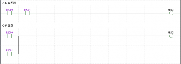
· AND circuit (also called serial circuit)
Connect a contact to the coil side by side.
If all the conditions are not completed, the circuit will not be connected to the end.
In this case, only “R2000: ON”, “R2001: ON” is “MR001: ON”.
| Switch1(R2000) | Switch2(R2001) | Coil(MR001) |
| OFF | OFF | OFF |
| ON | OFF | OFF |
| OFF | ON | OFF |
| ON | ON | ON |
· OR circuit (also called parallel circuit)
Connect vertically and a contacts to the coil.
If one condition is met, the circuit will be connected.
In this case, it is “MR001: ON” if “R2000: ON” or “R2001: ON”.
| Switch1(R2000) | Switch2(R2001) | Coil(MR001) |
| OFF | OFF | OFF |
| ON | OFF | ON |
| OFF | ON | ON |
| ON | ON | ON |
The operation is complete with the condition and the operation is an AND circuit, the operation of any one is OR circuit
NAND circuit and NOR circuit
The NAND circuit and the NOR circuit mean the opposite of the AND circuit and the OR circuit (NOT), respectively.
Therefore, the operation of the coil is completely opposite.
First, I will explain the NAND circuit.
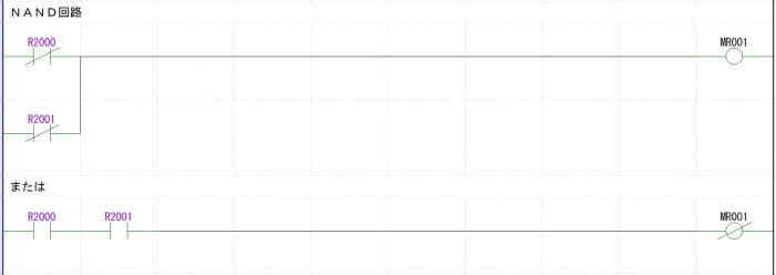
· NAND circuit
As you can see from the table below, the coil turns off when all the switches are ON.
Therefore, it can be made by setting the switch to b contact in parallel.
It is the reverse of the operation of the AND circuit. Therefore, it is also possible to make an AND circuit and make the coil NOT circuit.
| Switch1(R2000) | Switch2(R2001) | Coil(MR001) |
| OFF | OFF | ON |
| ON | OFF | ON |
| OFF | ON | ON |
| ON | ON | OFF |
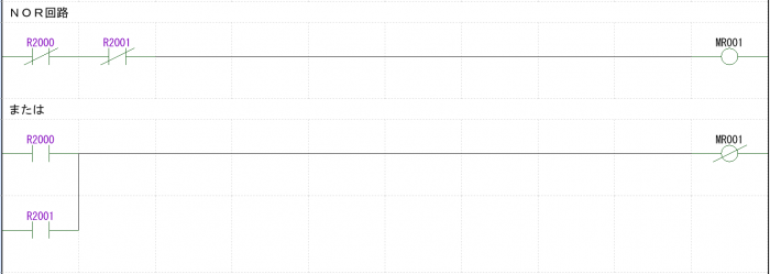
· NOR circuit
As you can see from the table below, the coil turns ON only when all the switches are OFF.
Therefore, you can make it by turning the switch to b contact in series.
It is the reverse of the operation of the OR circuit. Therefore, it is also possible to make an OR circuit and make the coil NOT circuit.
| Switch1(R2000) | Switch2(R2001) | Coil(MR001) |
| OFF | OFF | ON |
| ON | OFF | OFF |
| OFF | ON | OFF |
| ON | ON | OFF |
The NAND circuit is the reverse of the AND circuit, the NOR circuit behaves in the opposite direction of the OR circuit
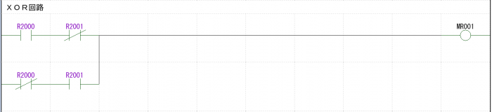
XOR circuit
It is also called exclusive OR circuit.
Although it may not be used much, you can express the behavior as shown in the table below.
When either switch 1 or 2 is ON, the coil turns ON (exclusive) circuit.
| Switch1(R2000) | Switch2(R2001) | Coil(MR001) |
| OFF | OFF | OFF |
| ON | OFF | ON |
| OFF | ON | ON |
| ON | ON | OFF |
The XOR circuit is used with exclusive control.
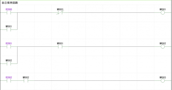
Self-holding circuit (self-hold circuit)
I will explain the self-holding circuit.
Also called a self-hold circuit, A circuit that continues to turn on the coil regardless of releasing the switch (switch OFF) once it is pressed .
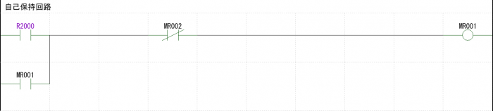
I will explain the flow of movement.
When the switch is pressed, the coil is connected and the coil turns ON. Then turn on the coil switch.
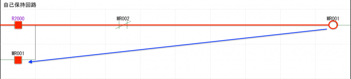
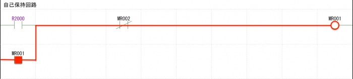
Since the coil was ON at the previous cycle at the next cycle, the coil switch is turned ON.
The switch will be connected to the coil and the coil will continue to turn ON.
The ON / OFF of switch R20000 does not matter at this cycle.
In the self-holding circuit, once the coil turns ON it can not be turned OFF, so here the switch MR002 for coil OFF is put in the circuit with b contact.
When turning ON MR002 while the coil is ON, the coil turns OFF.
Be careful not to be unable to control with deadlock (the coil can not be turned off).
Also, in terms of using coils, be careful with double coils.
If there are two or more coils with the same output name, it will not work properly.
The coil can be kept ON with a single switch operation. However, note Deadlock
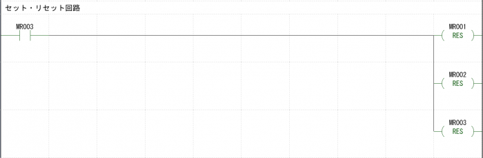
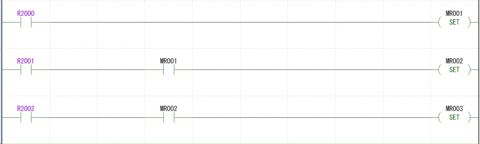
Set / reset circuit
The set / reset circuit is a circuit that holds itself. Therefore, ON is set and OFF is reset.
It is the same as the self-holding circuit and how to draw it is different.
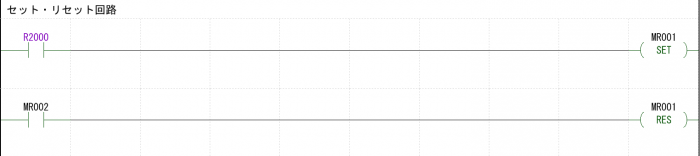
Let’s take care with resetting so that you can not control due to deadlock (the coil can not be turned off).
When using the set / reset output, let’s make the reset output at the same time after putting the set output.
Doing so prevents deadlocks. Moreover, it can prevent forgetting to move.
The same drawing method as self-maintenance is different. Likewise, note deadlock
Alternate circuit (flip-flop circuit)
The alternate circuit repeats ON / OFF alternately each time you press the switch.
It is also called a flip-flop circuit.
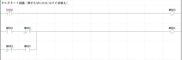
I will explain the move from OFF → ON.
Turning ON the switch turns ON only one cycle scan pressed with the rising pulse. Coil turns ON at that timing.
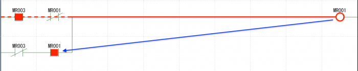
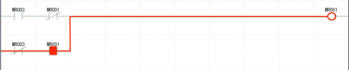
The rising pulse of the switch is cut off at the next cycle.
However, because the coil is ON at the previous cycle, the coil switch turns ON and self-holding is applied.
Coil ON / OFF switches each time the
switch is pressed
The following books are easy to understand in detail as sequence control.
Please refer if you do not mind otherwise.
図解入門よくわかる最新シーケンス制御と回路図の基本 (How‐nual Visual Guide Book)
Basic stage circuit
I think that sequence control will be done step by step when program is written by ladder circuit.
By controlling step by step, control will progress one after another.
I will briefly explain the stepwise sequence movement at that time.
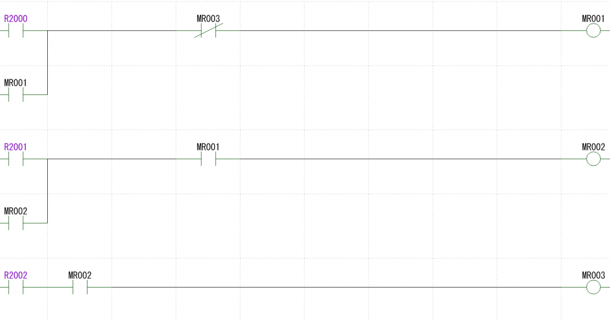
Step circuit of self-holding circuit
I put an example as a step circuit of a self-holding circuit below.
There are various patterns for making, so I think that you should make it easier for yourself to do.
As a flow of control,
“R2000 switch ON” → “first step processing” → “R2001 switch ON” → “second step processing” → “R2002 switch ON” → “processing end”
.
If you want to process with only the first stage processing, you can connect it next to move with AND circuit of “MR001: a contact” and “MR002: b contact”.
stage reset circuit stage circuit
It becomes an equivalent circuit made by set reset of the self-holding stage circuit earlier.
It is the same as the control flow,
“R2000 switch ON” → “first step processing” → “R2001 switch ON” → “second step processing” → “R2002 switch ON” → “processing end”
.
If you also want to process with just the first step processing, you can connect it next to move with the AND circuit of “MR001: a contact” and “MR002: b contact”.
Proceed with control in the step circuit and make a series of actions
Devices of ladder circuit
I will explain a little bit about what I am careful about when I draw a ladder.
· Reduction in the visibility of parallel circuits
· Separate from command, interlock, output
· In case of solenoid valve control by output
Reducing the visibility of parallel circuits
Write a parallel circuit as follows.
However, as the number of switches in the parallel circuit increases more and more, the circuit grows vertically and it becomes very hard to see in the visual program.
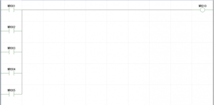
In that case, you can create an equivalent circuit as follows.
To make the parallel in series The AND circuit and the NOT circuit make it the same circuit.
It will be a little hard to understand, but as a program it will be very easy to see.
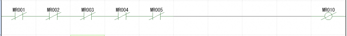
Reduce mistakes by making ladder circuits as easy as possible
Malfunction prevention
I said basic is to make inputs and outputs as simple as possible. (Human error, prevention of bugs)
Besides that, there are caveats, basically we will draw in mind the prevention of malfunction.
· Do not use the input as it is.
Instead of leaving the input as it is, use it based on the prevention of malfunction.
I think that there is no problem even if you use the place where malfunction does not occur as it is.
When the sensor is on the standby side, when two points on the operating side are taken, it judges the standby side and the operating side from the state of the two sensors and uses it for the program.
It can not be said that sensors, switches, etc. will not break.
This is because we will not let the program advance in case of breakdown.
• Do not use motion commands as output.
I think that there is no problem even if you use the place where malfunction does not occur also as it is.
Use interlock (monitor / judge the state where operation is possible).
Always monitor and judge the condition for the output operation.
Pass it to the output with command + interlock.
Use input / output for preventing malfunction
In case of solenoid valve control in output
It is a point of improvement when using single solenoid or double solenoid in output.
When controlling the double solenoid valve, I think that 2 point output is connected.
Depending on the control state, both OFF and ON one way ON, but normally both ON can not be done.
Therefore, it is a method not to make both ON as control.
Also, if you program the double solenoid valve to control the single solenoid valve, it will be easier to correct the program when changing from single to double.
· Self-holding circuit
As a feature, R50000 and R50001 are not turned ON at the same time.
For example, when MR000 (MR010, MR011 is ON) turns ON MR1000 turns ON once.
At that cycle, R50000 does not turn on, and the circuit of R50001 is turned off. (R 50000, R 50001 turn OFF)
R50001 turns on at the next cycle.
Here, MR 100 (both output OFF) is making switch when you want to cut both.
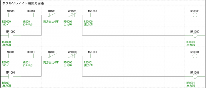
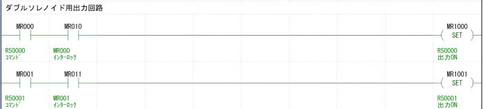
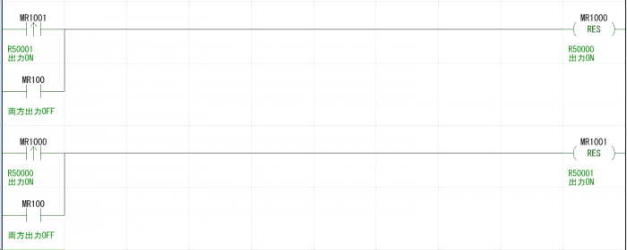
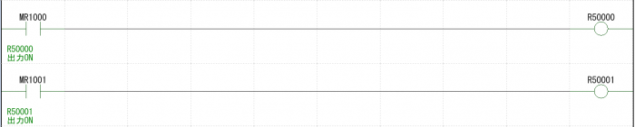
• Set reset circuit
It becomes the equivalent of the self-holding circuit the previous time.
Likewise, R50000 and R50001 are not turned ON at the same time.
However, when MR000 or MR001 (when MR010, MR011 is ON) turns ON, there is no cycle of both R50000 and R50001 OFF.
It turns ON / OFF immediately (at that cycle).
With solenoid valve control, making a circuit with a double solenoid makes it possible to respond to changes immediately
The following books are easy to understand in detail as sequence control.
Please refer if you do not mind otherwise.