Categories
Electrical and electrical / electronic design

Electric design 3 How to select power supply and circuit breaker unexpectedly not known

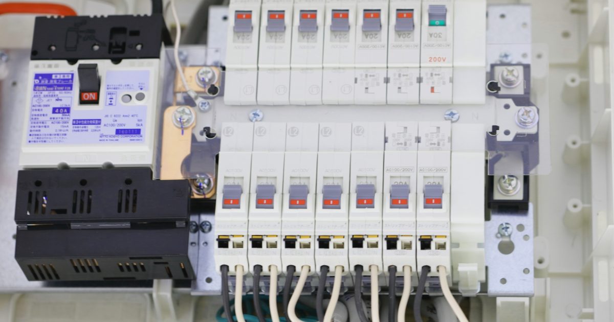
Do not know as it is known, how to select power supply and circuit breaker

Selection of power supply is the foundation of equipment and equipment.
Depending on this selection, the countries, areas of use, and methods of use are largely restricted.
Therefore, let’s think first.
The power supply here is a low voltage (AC 1000 V or less) talk.
Especially it is the selection method for equipment and equipment.

I would like to talk about power selection (AC) and selection of circuit breakers.

Power Supply Selection

First of all I would like to select the power supply.
We will select power supply for equipment and equipment as we select power supply.
There is a necessity of choosing the power source mainly depending on the place, type and usage to use
.
Flow in power selection

1. Voltage check mainly for areas to be used
2. Power supply stability
3. Selection of commercial voltage (single phase, three phase) to be used
4. Selection of equipment to be used

Depending on the equipment used, 3 and 4 may be reversed.
If you want to use it in various areas, if the power supply and the used power supply which are absolutely supplied as applications are different, you can also change it with a transformer etc, so please take it into consideration.

Verify the voltage of the area mainly used

This is not the case when the power supply is other than the commercial power supply, but check the voltage of the main use area of equipment and equipment to be designed from now.

The table below shows typical commercial power supply voltage.
However, voltages other than this table may be available.
Please use it for reference level.

Regional Commercial Supply Voltage (AC)


Region Household (single phase) Industrial (three phase) frequency
Japan 100 V 200 V 50/60 Hz
America 115 V 230 V 60 Hz
UK 230 V 400 V 50 Hz
Germany 230 V 400 V 50 Hz
China 220 V 380 V 50 Hz
India 220 V 380 V 50 Hz
Thai 230 V 400 V 50 Hz
Australia 240 V 415 V 50 Hz

Commercial voltage and frequency vary depending on the area.
Let’s check the supplied power supply of the area to be used and design it.
Also, if you are considering power generation from self-power generation or batteries, let’s check the power specifications there.

Voltage and frequency are different depending on the area. Confirm specification of power supply side

Power supply stability

Japan maintains a very good power supply stability.
However, there are many places where power supply stability is not good depending on the region.
As far as know, there is also a region that once the entire region in a few months may become a sudden power outage.

It also causes shortening of the life of the equipment.
Let’s got the information by the measurement and interviews to local people in the case of anxiety.

Voltage fluctuation rate
· Utilization rate of power supply

In some cases it is necessary to consider the following introductions and protect facilities and equipment.
Fluctuation of · voltage ⇨ AC stabilized power supply
· power supply interruption ⇨ uninterruptible power supply (UPS), etc.

There is a difference in stable power supply depending on the region

Selection of commercial voltage (single phase, three phase) to be used

Once you have grasped the power supply voltage of the country you mainly use, decide the commercial voltage to be used next.
This way of deciding how to use equipment and equipment and power consumption will also be decided.

It is characterized by industrial (3 phases) and household (single phase) respectively.
The following is a guide for each feature. Please put it in one corner.

Industrial (three-phase)

· Power efficiency is good (loss is small)
· The electricity price per unit is cheaper compared with home use (single phase)
· Large power can be used
· Use three-phase equipment
· Cable can be thinned
(Even with the same power consumption, the current can be reduced because the voltage is large)

Household (single phase)

· Do not have to dedicate electric contract
· Equipment can select household (single phase) power supply voltage
· Small and often moving like a tabletop machine
· Do not use in the factory, but use it in a general residence
· Do not use large electric power (usage current 15 A or less)
· Use DC power supply as equipment power supply, use only DC power supply
· No wiring work is necessary when connecting the power supply (when using the power plug)
· Consider safety

In addition, general current that can be used as home features is maximum 15 A
In Japan, 1500 W is the maximum output (1200 W for most products including safety factor) because it is 100 V.
In the United States, 1725 W (1400 W including safety factor) will be the maximum output.

As a supplement (home plug shape)
The shape of the power plug is as follows.
Please check the details of the corresponding area etc from the quoted place.

Aタイプ Bタイプ Cタイプ B3タイプ BFタイプ SEタイプ Oタイプ
海外の家庭用電源Aタイプ 海外の家庭用電源Bタイプ 海外の家庭用電源Cタイプ 海外の家庭用電源B3タイプ 海外の家庭用電源BFタイプ 海外の家庭用電源SEタイプ 海外の家庭用電源Oタイプ

TravelersCafeWorldGallery:Quote from overseas outlet / plug shape and list of voltage types

When using electricity charges or large electric power, for industrial use (three phases). When emphasis on usability select home use (single phase)

Selection of equipment to be used

It is necessary to select the power supply voltage of equipment used for equipment and equipment.
As a rough selection, we divided into industrial (three-phase), household (single phase) and power type, but I will check the equipment to see if it matches the voltage to be used.

Especially when special power supply is required or only specific power supply is necessary etc.

Required confirmation for device selection

· Check available power supply
· Check whether there is a change due to frequency
· Check if there is an alternative item to be applied to the power supply
· Confirmation of power consumption and total power consumption

If it is inevitable usable power supply does not match, it is necessary to redo “select commercial voltage (single phase, 3 phase) to use” again or change the power supply by transformer etc etc.

Confirm whether special and specific power supply is necessary for use equipment

This time I talked about AC (AC) mainly as a commercial power supply, but it is the same also in direct current.
The way of thinking after converting it to direct current in equipment is also the same.

Next I will talk about circuit breaker.
The following books will be helpful too, so please take a look if you are interested.
選び方・使い方 遮断器・開閉器

About circuit breakers

Next, I would like to talk about selection of circuit breaker.
A circuit breaker (commonly called a breaker) is an important device to draw from the power supply to equipment and equipment.

It is incorporated in the equipment itself, attached to the power board, and is used in various places and distribution plants in the home.
Selection of the wire to be connected must be larger than the capacity of the circuit breaker.

I would like to select the electric wire itself next time.

Purpose of breaker

There is a fuse in what works like a circuit breaker.
There are several purposes and the following functions are incorporated.

Breaker objective

· Circuit opening and closing
· Prevention of burnout of electric wire
· Prevent device failure
· Safety consideration to the human body

I described the circuit breaker for the purpose as the type of the corresponding circuit breaker.
Please consider it as a guide as it differs somewhat depending on selection and usage.

Corresponding Circuit Type
· Circuit opening / closing
Switch
Safety breaker (wiring breaker)
Electromagnetic contactor
Electromagnetic switchgear (electromagnetic contactor + thermal relay)
Earth leakage breaker (earth leakage breaker)
Circuit protector (AC, DC)

• Prevent burnout of wire
Fuse (temperature, current)
Safety breaker (wiring breaker)
Earth leakage breaker (earth leakage breaker)
Electromagnetic switchgear (electromagnetic contactor + thermal relay)
Circuit protector (AC, DC)

· Device malfunction prevention
Circuit protector (AC, DC)

· Safety consideration to human body
Earth leakage breaker (earth leakage breaker)

In addition to circuit breakers, there are many ones that have similar protective functions on the equipment itself.
For example, protection circuit such as hiccup of switching power supply is one of them.

Use circuit breaker according to purpose

Selection of circuit breaker

I will talk about the type of circuit breaker briefly explained earlier.
Among them, I mentioned the points to consider when selecting.

Examples of circuit breakers in distribution boards
分電盤内の例

Safety breaker (wiring breaker)

It is a general circuit breaker like switchgear + fuse that can be used many times .
It is common to install instead of the switch.

There are the following concepts of selection.
Selection of Safety Breaker (Circuit Breaker)

· I want to open and close circuits as main circuit and branch circuit
· I want to prevent burnout of electric wire
· The withstand current capacity of the wire is lowered
· I want to recover earlier than fuse

operation time
Even if it exceeds the rated value (display value) it does not fall immediately (does not trip)
There are the following provisions.


Rated current Operating time
1.25 times the rated current twice the rated current
30 A or less 60 min or less 2 min or less
30 A – 50 A 60 min or less 4 min or less
50 A ~ 100 A 120 min or less 6 min or less

Even if the rated current is exceeded, it does not operate immediately.
Therefore, please select it taking into consideration the current to be used and the safety factor of the electric wire used.

Safety breaker is “switchgear + fuse that can be used many times”

About earth leakage breaker (Earth leakage circuit breaker)

The earth leakage breaker (earth leakage circuit breaker) is like “wiring breaker + ground fault monitor” .

Electric shock by earth fault (leakage) and function to prevent fire are attached.
To prevent electric shock from a ground fault (earth leakage), earth (ground) is common, but it is used in combination.

It is about the installation standard of earth leakage circuit breaker in case of Japan.
※ The contents of this section are approximate. Because there is possibility of revision,「電気設備の技術基準の解釈の解説

Selection of earth leakage breaker (earth leakage breaker)

· Use in a wet place
· Fire prohibited place such as pyrotechnic cabinet etc
· There is no mechanism for automatically shutting off when a ground fault is detected
· Place omitted for earth (ground)
As an exception
· Use the equipment at power stations, substations, etc.
· Use in a dry place
· Use it at 150 V or less in places other than moisture
· The equipment is covered with rubber, synthetic resin or other insulation
· Contact protective measures (measures not touched easily) have been done
· Earth (earth) resistance of C · D type grounding work is 3 Ω or less

The circuit is shut off by the current (sensitivity current) at the time of leakage.
As another method of classification, classify according to the operation time (time to shut off).

Type of sensitivity current
(Leakage current due to leakage current)
· High sensitivity type 30 mA or less
· Medium sensitivity type 1000 mA or less

Type of response speed (time until operation)


type (shape) operation time corresponding function
High speed type Within 0.1 s Electric shock prevention
time delay within 2 s burnout prevention
Infinite time form Within 0.3 s, depending on sensitivity current Burnout prevention

Sensitivity current of less than 15 mA, response speed less than 0.1 s is selected for earth leakage circuit breaker at earth omitted (300 V or less)

As a rough guide of the selection method in the function, it is as follows.


Sensitivity current Operating speed Earth (ground) Corresponding function
~ 15 mA Within 0.1 s No ground, C / D type ground Electric shock prevention
~ 15 mA Over 0.1 s C · D grounding Fire prevention
16 mA to 500 mA Within 0.1 s C · D grounding Electric shock prevention
16 mA ~ 500 mA 0.1 s over C · D grounding fire prevention
501 mA ~ Within 0.1 s C / D grounding Fire prevention
501 mA ~ 0.1 s over C · D grounding fire prevention

There are standards for setting earth leakage breakers in Japan. It is necessary when monitoring earth faults.

About electromagnetic contactor and electromagnetic switch

Basically both are mainly used when connected to a motor or an electric heater.
It can control opening / closing of the circuit itself, also called magnetic switch from the feature.

The relationship between the electromagnetic contactor and the electromagnetic switch is as follows.
Electromagnetic switch = electromagnetic contactor + thermal relay

·thermal relay
Monitor the wire temperature to shut off the circuit by overload or short circuit.

electromagnetic contactor selection

· I want to control the opening and closing of the circuit (remote)
· No load fluctuation

Selection of electromagnetic switch (electromagnetic contactor + thermal relay)

· I want to control the opening and closing of the circuit (remote)
· Use a motor or an electric heater (there is load fluctuation)
· I want to shut down the circuit by overload or short circuit
(Monitor electric wire temperature)

important point
· Setting of thermal relay
At the start of the motor, a large current (about 7 times the rating) flows for several seconds.
Depending on the setting, malfunction may occur at startup.
Let’s check the characteristic curve and adjust it at about 120% overload.

· Consideration of surge absorption
If you are using a large motor (large inductive load), the counter electromotive voltage will occur when opening the circuit.
This will markedly reduce the durability of the switch.
Therefore, it is necessary to suppress the counter electromotive force with a surge absorbing varistor or the like.

Especially when you want to control opening / closing of the circuit (remote)

Circuit protector

It is a circuit breaker made on the premise of protection of the control circuit of the electronic circuit and the load, load.
It becomes a circuit breaker whose operation until shutdown is fast.

Selection of circuit protector

· Control circuit, I want to protect the load
· I want to block low capacity
· I also want to shut off the DC (DC) circuit
· Just a good rated current can not be found
(The rated current lineup is fine)
· I want to protect the secondary side wiring

Circuit breaker made on the premise of load protection

Household circuit breaker

Of course we also use circuit breakers in the home.
· Examples of distribution boards for household use (earth leakage circuit breaker, wiring breaker)
家庭用の遮断器の例

Normally, I think that the circuit breakers for households are configured as follows.

Ampere breaker (breaker with contract current value)
  ↓
Earth leakage circuit breaker (breaker with leakage test button)
  ↓
Circuit breaker (small breaker around)

I would like to explain how to deal with each breaker fault.
Anyone can recover if you cope without hurting.

Also, I have listed the possible factors, so please check as preventing recurrence.

If the ampere breaker has failed (tripped)

(Breaker with contract current value written)
Total electricity consumption in home exceeds contract value.

Let’s make the following correspondence.

1. Identify where you are using high power
2. Do not use devices that use large electric power at the same time
3. Stagger the timing of using devices that use large power

Power used exceeds contract value

If the earth leakage circuit breaker fails (trips)

(Breaker with leakage test button)
There is a possibility of electric leakage somewhere.
Try not to turn it on until you can check it.

If safety inside the house is confirmed, let’s correspond in the following order.

1. Turn off all wiring breakers
2. Turn on earth leakage circuit breaker
(At the time of a trip, the lever is temporarily stopped at the intermediate position, so OFF → ON once)
3. Turn on the circuit breaker one by one
4. When the earth leakage circuit breaker turns OFF again, check the corresponding position of the circuit breaker in the OFF state

There is a possibility that electric leakage is occurring somewhere

Circuit breaker failed (tripped)

It consumes a lot of electricity in part.
Usually, because the interrupter for wiring in the home is 15 A, if you use 3000 W under one circuit breaker it will fall within 2 minutes.

Let’s make the following correspondence.

1. Do you use instruments simultaneously with octopus foot wiring
2. Do not use large power at the same outlet, nearby outlet
3. If you really want to use a large amount of electricity, have an additional circuit created

Although it is not recommended, in the case of using for a short time, the following can be done due to the characteristics.
· Use slightly beyond 1500 W
· Use about 3000 W for about 1 minute

I use a lot of electricity at the same outlet

Categories
Electrical and electrical / electronic design

Electrical design 2 Concept of safety category for maintaining functions

Concept of safety category for maintaining functions

Safety categories are named “safe”, so it tends to be confused with “safety”, but it is not.
Safe Name of robustness / tolerance level that you can maintain function .

The safety category is the degree of “strength of maintenance” of “safety function”.
Therefore, the safety function (safety) is another problem.

The way of thinking is “function preservation” , which makes it a very useful reference other than safety functions.
I would like to talk about it this time.

Concept of Safety Category

As I mentioned briefly earlier, the safety category is a level of robustness and durability that “safety function” can be maintained.
This way of thinking can be thought of as a control as well, if it says either, it becomes the way of thinking of the robustness and tolerance of the function on the hardware side.

It is also related to risk assessment “probability of injury” , lowering the risk level of risk assessment Also useful.

The way of thinking is consolidated in hardware reliability “functional reliability” to maintain quality of product function It will be a story to do.

If constructed in the same way as this safety category, the robustness and durability of the functions normally used are also similarly raised.

“Safety category” ≒ “Maintenance level of function”

Therefore, it is possible to use it for safety other than safety, to maintain the function.

Categorization

The level of function maintenance (category) explained, can be easily divided into the following five.

· Category B
· Category 1
· Category 2
· Category 3
· Category 4

The lower you go, the more robustness and tolerance will be.
These are based on safety category classification and the necessary requirement ISO 13849-1.
Next, I will explain how it is organized by category.

Categories can be divided into 5

Category B

カテゴリB 安全機能維持には使用できません。

Normally, the desired function can be realized . (Level at which the safety function operates)

It becomes a series of flow with “input → function → output”.

If something happens, the function will be a level category that stops the operation.
Therefore, category B does not hold as a circuit for maintaining safety functions.
Let’s design it as intrinsically safe (safety is fundamentally established before safety functions are necessary) as safety.

Category B can not be used to maintain safety function

Category 1

カテゴリ1 吟味された構成要素を使用する

satisfy the condition of category B and using the examined component , safety is obeying the safety principle .

Just like Category B, “Input -> Function -> Output” and flow will be together.

What are the examined components
· High reliability and reduced fault possibility
· Certainly operating in the safe direction in case of failure
· Things that have been widely used for safety

Category B + It is a way of thinking of using reliable parts.

Category 1 is to use the examined components

Category 2

カテゴリ2はカテゴリB+点検機器が取り付いている

satisfy the condition of category B and have inspection function , safety is safety It follows that principle .

“Input -> function -> output” and the flow of flow are the same.
Moreover, “inspection function” is added form.

Inspection function is a function to check manually or automatically whether the function is maintained at an arbitrary timing.
Based on the inspection result, we decide whether to operate.

Category 2 added inspection function

Category 3

カテゴリ3、4 冗長化により2重回路を組み常に監視をする
または、
カテゴリ3、4 冗長化により2重回路を組み常に監視をする

satisfy the condition of category B and have monitoring function , redundancy Dual circuit) , safety is Safety principle .

“Input 1 → Function 1 → Output 1”, “Input 2 → Function 2 → Output 2” and the flow of operation is divided into two lines.
Both functions are the same.

From category 3, it is considered as a very important part and thus it is necessary to make it “redundant” (duplicated).

“Redundancy” is a circuit or system that operates without problems even if one of the functions is duplicated and the other remains even if one of them fails.
This is a very good method as a way to increase functional reliability.
However, the cost is double that amount.

Also, since there is a monitoring function, it can detect when a failure occurs.
Category 3 does not guarantee until multiple duplicate failures (accumulation of failures).

Category 3 redundancy and monitoring function

Category 4

It is the same as Category 3 as a circuit.

satisfy the condition of category 3 and tolerance to failure accumulation .

As with category 3, the flow of operation is divided into two lines as “input 1 → function 1 → output 1”, “input 2 → function 2 → output 2”.
The function of both systems is the same.

What is tolerance to failure accumulation
· Detect if a single fault occurs when the function is executed or when a fault occurs
· The function is not compromised by multiple duplicate failures (accumulation of failure)

Categories 3 and 4 are constructed in the same way in important parts such as airplane system and bank system system.
Think about similar places where you can not miss as a function.

Category 4 further improves resistance to category 3

Like these, the same idea as the safety category is very useful for maintaining the function.
It is necessary to think about how to maintain the function at design time.
Please respond according to the situation.

Categories
Electrical and electrical / electronic design

Electrical design 1 Electrical and electrical design corresponding to heat

Font size = “6”> Electrical and electrical design corresponding to heat

I will think about the influence of control board and temperature of electrical equipment / electric equipment as electric / electric design corresponding to heat.
I think that the safety factor etc. at the time of design will differ depending on the company, so I would be pleased if you read it with reference level.

Influence of control components and electronic components given by heat

There are three possible influences:

·lifespan
·safety
·function

· Longevity

Life span reduction can be expressed by “Arrhenius equation” which is an expression for predicting the rate of chemical reaction at a certain temperature.
Degradation of grease and oil deteriorates the life of parts that use it.
Moreover, its lifetime is not proportional to temperature, and its lifetime shrinks acceleratingly with temperature rise.
Especially for capacitors in electronic components talks.

· Safety

Basically it comes in contact with the skin as heat, it becomes whether the thing by heat in the atmosphere is safe.
Low temperature burns (contact with skin for about 40 ° C for a long time)
Rapid temperature rise
Contact in hot state and unaware
Besides this, when harmful gas is generated due to temperature rise, it needs to be taken into consideration.

– Function

In particular here I would like to explain ‘migration’ .
Migration has elements other than fever. In the first place, migration means that metal used as wiring or electrode moves over insulation, insulation resistance value decreases and failure / function degradation occurs due to insulation failure.
Migration has three types.
In the case of
Stress Migration
· Migration by metal being subjected to stress under temperature change environment
· Phenomena resulting in resistance increase and disconnection of wiring due to voids due to impurities or the like

Electromigration
· Migration by electron movement
· Easy to put on when the temperature is high
· Easy to handle when the current density is high

Ion Migration
· Electrochemical (accompanying electrolytic phenomenon) migration
· Easy to keep when the humidity is high

It is necessary to consider “life”, “safety”, “function” for control parts and electronic parts against heat

It will be helpful for books that are written in detail as thermal design.
Please refer to those who want to know more.
エレクトロニクスのための熱設計完全入門

Temperature design in control unit / control panel

I think that the way of thinking of heat itself is explained by the story of “The way of thinking of fever”.
This time we will explain the relation between the heat generation of the equipment and the heat dissipation of the electrical panel / control equipment box as an example.
The same way of thinking can be used in various places.
The contents to be considered in the temperature design inside the control device / control panel are

Calculation of calorific value
Calculation of heat dissipation

Calorific value calculation, heat radiation amount calculation.
The flow of design is as follows.
Design flow 1

For flow, calculate “calorific value” → “Calculate heat dissipation amount of (box)”.
Here, in the case of “calorific value”> “heat dissipation amount”, “ventilation opening” is provided as “radiator design” to calculate “natural ventilation heat radiation amount”.
Consider whether there is heat dissipation in ventilation (taking safety factor into account) more than “calorific value – heat dissipation amount”.
If it is still not enough, we will do “Calculate forced ventilation heat radiation amount” with fans etc. in the ventilation opening.

Then let’s consider the calculation of “calorific value” and “heat release amount”.
Below is an image diagram of heat generation and heat dissipation.
Box heat dissipation

· calorific value calculation

It is the sum of the calorific value of the equipment itself.
If the calorific value is unknown, please obtain the power consumption [W] from the current consumption of the equipment itself and the loss current.
I will give it as an example of a control panel.

· heat dissipation calculation

It will be the temperature to radiate to the surroundings from the box itself.
Board heat radiation
Board heat value
Here, we use the heat passage rate U [W / m 2 / K].
General control equipment box (iron · painted) is about 4 ~ 6 [W / m 2 / K], but it changes somewhat depending on the environment.
The target temperature inside the box here is set to the temperature at which the control life of the control equipment is calculated.
If there is more than one control device, set the lowest temperature among the temperatures that the device calculates in life calculation.
The effective heat radiation area is the surface area of ​​the box.

For example, assuming that the target inside temperature is 55 [° C.], the atmospheric temperature is 40 [° C.], the effective heat radiation area is 2 [m 2], and the heat amount is 1000 [W], when the heat passage rate is 5 [W / m 2 / K]
Qr = 5 * 2 * (55 – 40) = 150 [W]
Heat radiation design from the box itself Qr For heat generation quantity Q of the equipment, heat radiation design is required.
In this example, (1000-150) = 850 [W] further heat dissipation is required.
If you do not need estimate of heat transfer rate please skip to “heat radiation design”.

When the calorific value slightly exceeds the heat radiation amount (multiplied by the safety factor), it is necessary to respond to changes such as changing to a material with a high heat passage rate, increasing the effective heat radiation area with a heat sink or the like.
If the calorific value is still exceeded, it is necessary to consider the “heat dissipation design” described below.

Estimating Heat Transfer Ratio
If you do not know the heat transfer rate please estimate from the following.
Below is the cross section of the inside and the outside of the box.
Flow chart that heat flows through the wall
Heat Passing Ratio
. As a way of transferring heat, internal temperature T → board surface Th 1 → external plate surface Th 2 → external temperature (atmospheric temperature) T 0 will be transmitted.
The heat transfer coefficient h1 [W / m2 · K] inside the box, the heat transfer coefficient h2 [W / m2 · K] outside the box, the plate transfer rate is the plate thickness t [m] of the box, the box It is derived from the thermal conductivity λ [W / m · K].

To obtain this we need the following
heat transfer coefficient
The heat transfer coefficient h1 is obtained from the convective heat transfer coefficient ha inside the box and the heat transfer coefficient h2 is obtained from the convective heat transfer coefficient hb of the box outside and the radiative heat transfer coefficient hε.
The convective heat transfer coefficients ha and hb vary with the flow velocity of the fluid.

Below is a table of air heat transfer coefficient and wind speed.
Air heat transfer coefficient
In addition, radiative heat transfer coefficient h ε is heat dissipation due to radiation heat generated from the plate.
radiative heat transfer coefficient

5.67 * 10 ^ 8 is what is called the Stefan Boltzmann constant.
Ε is the emissivity and I think that it should be around 0.6 to 0.9. Also, I use Th1, Th2.
Although it is not accurate, I think that it is good at the middle (T – T 0) / 2 + T 0 inside and outside the box in estimation.

Example: emissivity 0.8, Th 2, 47.5 [° C], flow rate of the atmosphere in the box 1 [m / s], flow rate of atmosphere outside the box 0.5 [m / s], box thickness 0.003 [m] When the rate is 50 [W / m · K]
Atmospheric flow velocity 1 [m / s] → Convection heat transfer coefficient 8 [W / m 2 · K]
Atmospheric flow velocity 0.5 [m / s] → Convection heat transfer coefficient 4.5 [W / m 2 · K]

H 1 = 8 [W / m 2 · K]
(47.5 + 273.15) ^ 4- (40 + 273.15) ^ 4) / (47.5-40) = 4.5 + 5.78 = 10.28 [W / m 2 · K]
T / [lambda] = 0.003 / 50 = 0.00006 [W / m <2> K]
U = 1 / (1/8 + 0.00006 + 1 / 10.28) = 4.50 [W / m 2 · K]
I think that I will explain the way of thinking in the concept of fever.

If heat radiation can not be made in time, it is necessary to consider heat dissipation in “natural ventilation” “forced ventilation”

Heat radiation design inside the control device / control panel

We also made calculations for the amount of heat dissipation in the box.
In case of “calorific value”> “heat dissipation amount”, we will adopt the method to be described from now.
The amount of heat dissipation in the ventilation to speak under this should be “(heat release by ventilation)”> “calorific value” – “heat dissipation amount of (box)”.

Calculation with natural ventilation “Calculation of natural ventilation heat radiation”

Natural Ventilation Thermal Diagram
It is an example of natural ventilation heat radiation. In natural ventilation heat dissipation, there is a method to set the ventilation port so that the temperature inside the box approaches the ambient temperature. I will leave the movement of the gas to nature.
Calculation of heat radiation amount is as follows.
Natural ventilation heat radiation

natural ventilation value
I think that the atmosphere is usually air. The density of air is 1.154 [kg / m 3] and the specific heat of air is 1018 [J / kg ℃].

For example, the target inside temperature is set to 55 ° C., the temperature near the ceiling in the box is set to 58 ° C., the ambient temperature is set to 40 ° C., the area of ​​the ventilation opening for execution is 0.05 m 2, the height of the intake port-exhaust port is 0.3 m ] And
Heat radiation amount Q = 1018 * 1.154 * 0.05 * √ ((2 * 9.8 * 0.3 * (55 – 40)) / (273.15 – 40)) * (58 – 40) = 561.12 [W]

Heat generation amount 1000 [W]> heat radiation amount of box 150 [W] + natural ventilation heat radiation amount 561.12 [W] = 711.12 [W], so further heat radiation is required.
When the calorific value slightly exceeds the heat release amount (multiplied by the safety factor) like this, it is necessary to increase the effective ventilation area, increase the difference between the exhaust port and the intake port height, and so on. In some cases it is necessary to think about how to set the limit of ambient temperature (temperature limit on use). If we can not respond, we will consider heat dissipation in the next forced ventilation.

Calculation with forced ventilation “Calculation of forced ventilation heat radiation”

Forced ventilation heat dissipation
An example of forced ventilation heat dissipation. In forced ventilation heat radiation, unlike natural ventilation heat radiation, it is a method to forcibly move a gas with a fan or the like to bring the temperature inside the box close to the ambient temperature.

Calculation is as follows.
強制換気放熱風量

強制換気値

Normally, I think that the atmosphere is air. In that case the air density will be 1.154 [kg / m 3] and the specific heat of air will be 1018 [J / kg ℃].

For example, if the remaining required heat radiation amount is (heating value 1000 [W] – total heat radiation amount 711.12 [W]) = 288.88 [W], the in-box target temperature is 55 [° C.], and the ambient temperature is 40 [
V = 288.88 / (1.154 * 1018 * (55 – 40))
 = 0.0164 [m3 / min] and so on. (This value is the air volume)

When selecting, please find a fan more than this with the safety factor multiplied by this.
If there is no fan to be selected or if the heat exceeds the ventilation opening, it is necessary to limit the temperature within the design range by limiting the ambient temperature (temperature limit in use).

If heat radiation can not be made in time, it is necessary to consider heat dissipation in “natural ventilation” “forced ventilation”

In this way, it is necessary to solve the heat problem beforehand on the design.
It is invisible and inaccessible, but if you do not do it you will encounter serious eyes later.
Let’s raise the design accuracy as compared with what we did.


It will be a reference for books written as thermal design from various angles than what we have talked about until now.
It becomes a book of thermal design that can be used for electrical designers.