
Font size = “6”> Electrical and electrical design corresponding to heat
I will think about the influence of control board and temperature of electrical equipment / electric equipment as electric / electric design corresponding to heat.
I think that the safety factor etc. at the time of design will differ depending on the company, so I would be pleased if you read it with reference level.
Influence of control components and electronic components given by heat
There are three possible influences:
·safety
·function
· Longevity
Life span reduction can be expressed by “Arrhenius equation” which is an expression for predicting the rate of chemical reaction at a certain temperature.
Degradation of grease and oil deteriorates the life of parts that use it.
Moreover, its lifetime is not proportional to temperature, and its lifetime shrinks acceleratingly with temperature rise.
Especially for capacitors in electronic components talks.
· Safety
Basically it comes in contact with the skin as heat, it becomes whether the thing by heat in the atmosphere is safe.
Low temperature burns (contact with skin for about 40 ° C for a long time)
Rapid temperature rise
Contact in hot state and unaware
Besides this, when harmful gas is generated due to temperature rise, it needs to be taken into consideration.
– Function
In particular here I would like to explain ‘migration’ .
Migration has elements other than fever. In the first place, migration means that metal used as wiring or electrode moves over insulation, insulation resistance value decreases and failure / function degradation occurs due to insulation failure.
Migration has three types.
In the case of
Stress Migration
· Migration by metal being subjected to stress under temperature change environment
· Phenomena resulting in resistance increase and disconnection of wiring due to voids due to impurities or the like
Electromigration
· Migration by electron movement
· Easy to put on when the temperature is high
· Easy to handle when the current density is high
Ion Migration
· Electrochemical (accompanying electrolytic phenomenon) migration
· Easy to keep when the humidity is high
It is necessary to consider “life”, “safety”, “function” for control parts and electronic parts against heat
It will be helpful for books that are written in detail as thermal design.
Please refer to those who want to know more.
エレクトロニクスのための熱設計完全入門
Temperature design in control unit / control panel
I think that the way of thinking of heat itself is explained by the story of “The way of thinking of fever”.
This time we will explain the relation between the heat generation of the equipment and the heat dissipation of the electrical panel / control equipment box as an example.
The same way of thinking can be used in various places.
The contents to be considered in the temperature design inside the control device / control panel are
Calculation of heat dissipation
Calorific value calculation, heat radiation amount calculation.
The flow of design is as follows.
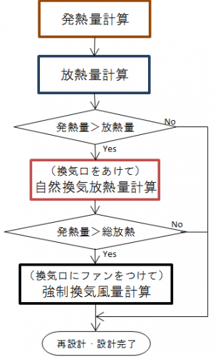
For flow, calculate “calorific value” → “Calculate heat dissipation amount of (box)”.
Here, in the case of “calorific value”> “heat dissipation amount”, “ventilation opening” is provided as “radiator design” to calculate “natural ventilation heat radiation amount”.
Consider whether there is heat dissipation in ventilation (taking safety factor into account) more than “calorific value – heat dissipation amount”.
If it is still not enough, we will do “Calculate forced ventilation heat radiation amount” with fans etc. in the ventilation opening.
Then let’s consider the calculation of “calorific value” and “heat release amount”.
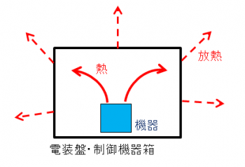
Below is an image diagram of heat generation and heat dissipation.
· calorific value calculation
It is the sum of the calorific value of the equipment itself.
If the calorific value is unknown, please obtain the power consumption [W] from the current consumption of the equipment itself and the loss current.
I will give it as an example of a control panel.
· heat dissipation calculation
It will be the temperature to radiate to the surroundings from the box itself.
![]()
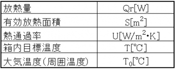
Here, we use the heat passage rate U [W / m 2 / K].
General control equipment box (iron · painted) is about 4 ~ 6 [W / m 2 / K], but it changes somewhat depending on the environment.
The target temperature inside the box here is set to the temperature at which the control life of the control equipment is calculated.
If there is more than one control device, set the lowest temperature among the temperatures that the device calculates in life calculation.
The effective heat radiation area is the surface area of the box.
For example, assuming that the target inside temperature is 55 [° C.], the atmospheric temperature is 40 [° C.], the effective heat radiation area is 2 [m 2], and the heat amount is 1000 [W], when the heat passage rate is 5 [W / m 2 / K]
Qr = 5 * 2 * (55 – 40) = 150 [W]
Heat radiation design from the box itself Qr For heat generation quantity Q of the equipment, heat radiation design is required.
In this example, (1000-150) = 850 [W] further heat dissipation is required.
If you do not need estimate of heat transfer rate please skip to “heat radiation design”.
When the calorific value slightly exceeds the heat radiation amount (multiplied by the safety factor), it is necessary to respond to changes such as changing to a material with a high heat passage rate, increasing the effective heat radiation area with a heat sink or the like.
If the calorific value is still exceeded, it is necessary to consider the “heat dissipation design” described below.
Estimating Heat Transfer Ratio
If you do not know the heat transfer rate please estimate from the following.
Below is the cross section of the inside and the outside of the box.
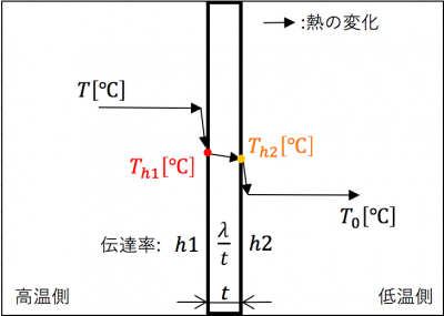
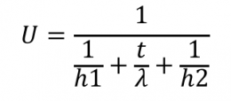
. As a way of transferring heat, internal temperature T → board surface Th 1 → external plate surface Th 2 → external temperature (atmospheric temperature) T 0 will be transmitted.
The heat transfer coefficient h1 [W / m2 · K] inside the box, the heat transfer coefficient h2 [W / m2 · K] outside the box, the plate transfer rate is the plate thickness t [m] of the box, the box It is derived from the thermal conductivity λ [W / m · K].
To obtain this we need the following
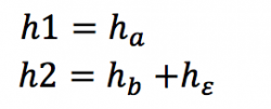
The heat transfer coefficient h1 is obtained from the convective heat transfer coefficient ha inside the box and the heat transfer coefficient h2 is obtained from the convective heat transfer coefficient hb of the box outside and the radiative heat transfer coefficient hε.
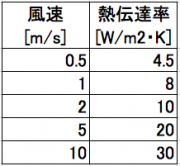
The convective heat transfer coefficients ha and hb vary with the flow velocity of the fluid.
Below is a table of air heat transfer coefficient and wind speed.
In addition, radiative heat transfer coefficient h ε is heat dissipation due to radiation heat generated from the plate.
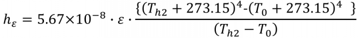
5.67 * 10 ^ 8 is what is called the Stefan Boltzmann constant.
Ε is the emissivity and I think that it should be around 0.6 to 0.9. Also, I use Th1, Th2.
Although it is not accurate, I think that it is good at the middle (T – T 0) / 2 + T 0 inside and outside the box in estimation.
Example: emissivity 0.8, Th 2, 47.5 [° C], flow rate of the atmosphere in the box 1 [m / s], flow rate of atmosphere outside the box 0.5 [m / s], box thickness 0.003 [m] When the rate is 50 [W / m · K]
Atmospheric flow velocity 1 [m / s] → Convection heat transfer coefficient 8 [W / m 2 · K]
Atmospheric flow velocity 0.5 [m / s] → Convection heat transfer coefficient 4.5 [W / m 2 · K]
H 1 = 8 [W / m 2 · K]
(47.5 + 273.15) ^ 4- (40 + 273.15) ^ 4) / (47.5-40) = 4.5 + 5.78 = 10.28 [W / m 2 · K]
T / [lambda] = 0.003 / 50 = 0.00006 [W / m <2> K]
U = 1 / (1/8 + 0.00006 + 1 / 10.28) = 4.50 [W / m 2 · K]
I think that I will explain the way of thinking in the concept of fever.
If heat radiation can not be made in time, it is necessary to consider heat dissipation in “natural ventilation” “forced ventilation”
Heat radiation design inside the control device / control panel
We also made calculations for the amount of heat dissipation in the box.
In case of “calorific value”> “heat dissipation amount”, we will adopt the method to be described from now.
The amount of heat dissipation in the ventilation to speak under this should be “(heat release by ventilation)”> “calorific value” – “heat dissipation amount of (box)”.
Calculation with natural ventilation “Calculation of natural ventilation heat radiation”
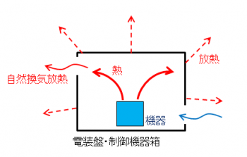
It is an example of natural ventilation heat radiation. In natural ventilation heat dissipation, there is a method to set the ventilation port so that the temperature inside the box approaches the ambient temperature. I will leave the movement of the gas to nature.
Calculation of heat radiation amount is as follows.
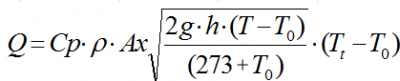
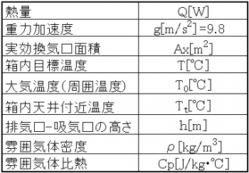
I think that the atmosphere is usually air. The density of air is 1.154 [kg / m 3] and the specific heat of air is 1018 [J / kg ℃].
For example, the target inside temperature is set to 55 ° C., the temperature near the ceiling in the box is set to 58 ° C., the ambient temperature is set to 40 ° C., the area of the ventilation opening for execution is 0.05 m 2, the height of the intake port-exhaust port is 0.3 m ] And
Heat radiation amount Q = 1018 * 1.154 * 0.05 * √ ((2 * 9.8 * 0.3 * (55 – 40)) / (273.15 – 40)) * (58 – 40) = 561.12 [W]
Heat generation amount 1000 [W]> heat radiation amount of box 150 [W] + natural ventilation heat radiation amount 561.12 [W] = 711.12 [W], so further heat radiation is required.
When the calorific value slightly exceeds the heat release amount (multiplied by the safety factor) like this, it is necessary to increase the effective ventilation area, increase the difference between the exhaust port and the intake port height, and so on. In some cases it is necessary to think about how to set the limit of ambient temperature (temperature limit on use). If we can not respond, we will consider heat dissipation in the next forced ventilation.
Calculation with forced ventilation “Calculation of forced ventilation heat radiation”
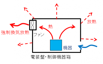
An example of forced ventilation heat dissipation. In forced ventilation heat radiation, unlike natural ventilation heat radiation, it is a method to forcibly move a gas with a fan or the like to bring the temperature inside the box close to the ambient temperature.
Calculation is as follows.
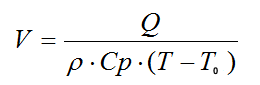
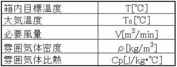
Normally, I think that the atmosphere is air. In that case the air density will be 1.154 [kg / m 3] and the specific heat of air will be 1018 [J / kg ℃].
For example, if the remaining required heat radiation amount is (heating value 1000 [W] – total heat radiation amount 711.12 [W]) = 288.88 [W], the in-box target temperature is 55 [° C.], and the ambient temperature is 40 [
V = 288.88 / (1.154 * 1018 * (55 – 40))
= 0.0164 [m3 / min] and so on. (This value is the air volume)
When selecting, please find a fan more than this with the safety factor multiplied by this.
If there is no fan to be selected or if the heat exceeds the ventilation opening, it is necessary to limit the temperature within the design range by limiting the ambient temperature (temperature limit in use).
If heat radiation can not be made in time, it is necessary to consider heat dissipation in “natural ventilation” “forced ventilation”
In this way, it is necessary to solve the heat problem beforehand on the design.
It is invisible and inaccessible, but if you do not do it you will encounter serious eyes later.
Let’s raise the design accuracy as compared with what we did.
It will be a reference for books written as thermal design from various angles than what we have talked about until now.
It becomes a book of thermal design that can be used for electrical designers.