
Factory automation (FA) systems use a wide range of communications, from coordinated control between PLCs and sensor ON/OFF signals to synchronized servo motor control and production data collection. However, with so many FA communication standards, including CC-Link, DeviceNet, PROFIBUS, EtherNet/IP, EtherCAT, PROFINET, CC-Link IE TSN, and Modbus, engineers often struggle to determine which standard is best suited to a particular application and how much communication speed is required.
The key is to select an FA communication system based on the connected devices and network level, communication cycle and synchronization accuracy, data volume and number of devices, and compatibility with existing equipment. Even a 1 Gbps standard does not automatically guarantee fast equipment response. Network design must account for data capacity, packet intervals, switch forwarding, and PLC scan times.
This article compares 12 representative protocols and explains cyclic communication, the roles of QoS, IGMP snooping and PoE, and practical methods for calculating RPI, heartbeat intervals, required bandwidth, and actual transmission times.
1. FA Network Levels and Their Applications
The terms “controller level” and “field level” describe application-based levels defined by what is connected. In contrast, “cyclic communication” describes a communication method defined by when data is exchanged. Distinguishing these concepts is the first step in network design.
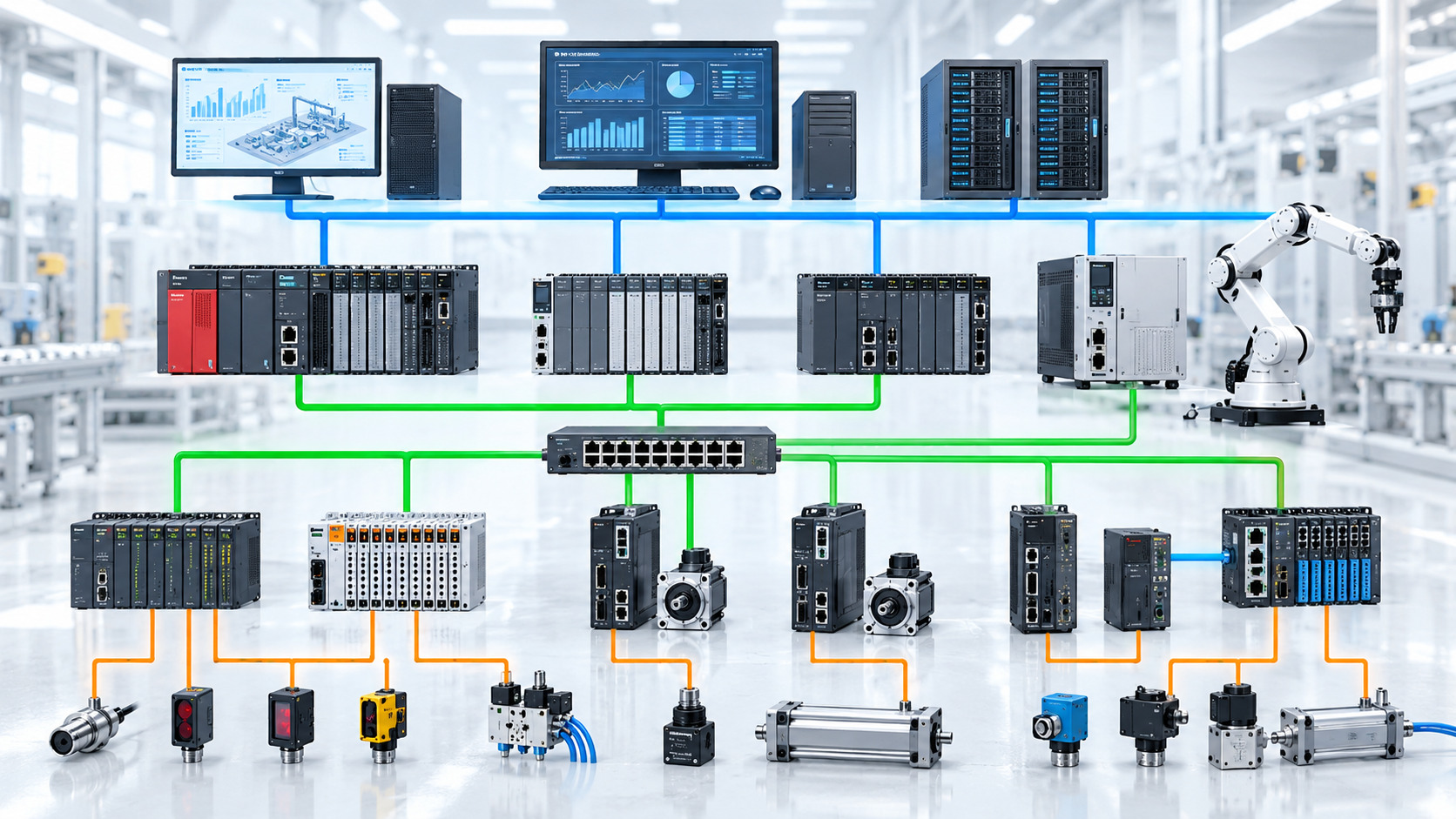
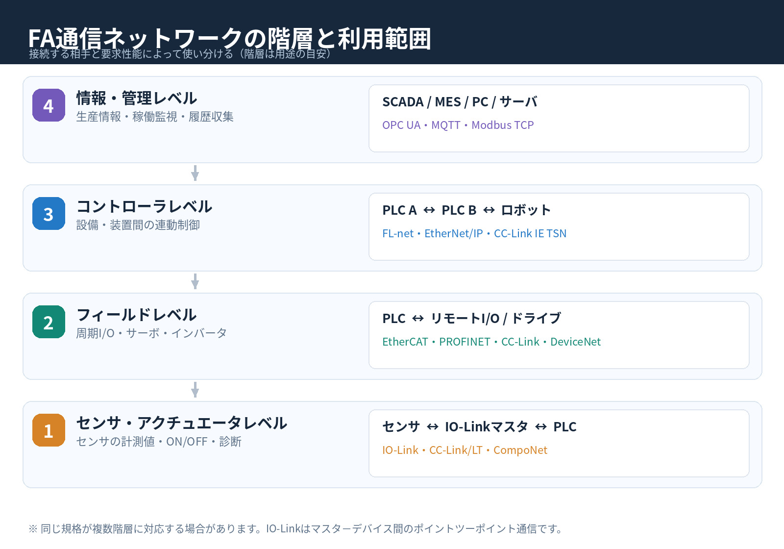
| Level | Main Connected Devices | Required Functions | Typical Communications |
|---|---|---|---|
| Information / Management | SCADA, MES, PCs, servers | Operational monitoring; collection of history and production results | OPC UA, MQTT, Modbus TCP |
| Controller | PLCs, CNCs, robot controllers | Coordinated line operation; data sharing between PLCs | FL-net, EtherNet/IP, CC-Link IE TSN |
| Field | PLCs, remote I/O, servo drives, inverters | Cyclic I/O, control commands, diagnostics | CC-Link, DeviceNet, PROFIBUS, EtherCAT, PROFINET |
| Sensor / Actuator | Photoelectric sensors, pressure sensors, solenoid valves, etc. | Reduced wiring; acquisition of measurements and status information | IO-Link, CC-Link/LT, CompoNet |
This application-based classification is intended to aid understanding; it is not a rigid four-level structure prescribed by a standard. For example, EtherNet/IP can be used both between PLCs and for remote I/O. IO-Link is a point-to-point connection between a sensor and an IO-Link master; it is not Ethernet itself.
2. Classifying FA Communications Along Three Axes: Physical Medium, Application, and Data Exchange Method
2-1. Classification by Communication Medium
| Category | Representative Examples | Design Considerations |
|---|---|---|
| Serial / Conventional Fieldbus | CC-Link, PROFIBUS DP, Modbus RTU | Can cover long distances even at relatively low speeds. Cable length, termination resistors, and branching conditions are important. |
| CAN-based | DeviceNet, CANopen | Suited to compact devices and distributed control. Consider the relationship between data rate and trunk length. |
| Dedicated Physical Layer / Reduced-Wiring Systems | CC-Link/LT, CompoNet, IO-Link | Suited to low-point-count I/O and sensors. Check dedicated cabling and master requirements. |
| Industrial Ethernet | EtherNet/IP, EtherCAT, PROFINET, CC-Link IE TSN, Modbus TCP | Suited to high-speed communication and device integration, but an Ethernet port alone does not establish protocol compatibility. |
2-2. Communication Speed (bps), Data Volume (bytes), and Response Time (ms) Are Different
- Communication speed (physical link speed): The bit rate the communication link can carry per second, such as 100 Mbps.
- Communication capacity (data volume): The number of bytes transmitted per cycle or message. Devices also have separate limits on maximum link points, message length, and connection count.
- Effective throughput: The amount of application data actually transferred after accounting for headers and transmission overhead.
- Update interval / RPI: How often data is updated, expressed in milliseconds.
- Response time and jitter: The delay from an input change to its effect at the output, and the variation in that delay.
Therefore, a 1 Gbps link does not necessarily make a machine respond ten times faster than a 100 Mbps link. Actual response depends on the PLC’s internal processing cycle, communication interval, receiving-device processing, and other network traffic.
The following book was used as a reference during the design process: Practical Guide to Servo Motor Control, Adjustment, and Diagnostics: A Troubleshooting Framework Based on Waveforms and Physics for Vibration, Abnormal Noise, and Positioning Accuracy
3. Comparison of 12 Representative FA Communication Protocols
We begin by comparing the eight originally specified protocols with EtherCAT, PROFINET, CC-Link IE TSN, and Modbus added. The distances shown are representative examples and do not guarantee the maximum distances specified by standards or products for every network configuration.
| Communication Protocol | Main Application / Level | Typical Physical Data Rate | Typical Distance / Constraints | Key Characteristics |
|---|---|---|---|---|
| CC-Link | Field | 156 kbps–10 Mbps | 100 m at 10 Mbps / 1,200 m at 156 kbps (depending on trunk conditions) | Conventional remote I/O and inverters |
| CC-Link/LT | Sensors / Low-point-count I/O | 156 kbps / 625 kbps / 2.5 Mbps | Trunk length: 35 m (2.5 Mbps) to 500 m (156 kbps) | Reduced wiring and branch connections |
| DeviceNet | Field | 125 / 250 / 500 kbps | Trunk length: 100 m (500 kbps) to 500 m (125 kbps, specified cable) | Combination of CAN and CIP |
| PROFIBUS DP | Field | 9.6 kbps–12 Mbps | 100 m per segment at 12 Mbps (RS-485) | Distributed I/O and drives |
| FL-net | Primarily controller level | Depends on Ethernet implementation (examples support 10 / 100 / 1000 Mbps) | Typically 100 m per link over twisted-pair cable | Common-memory sharing and messaging between PLCs |
| CompoNet | Sensor / Field | 93.75 kbps / 1.5 / 3 / 4 Mbps | Short distances at 4 Mbps; some low-speed repeater configurations extend to 1,500 m | Reduced wiring for many distributed low-point-count I/O devices |
| EtherNet/IP | Controller / Field | 10 / 100 Mbps and devices supporting 1 Gbps, etc. | Typically 100 m per link over copper Ethernet | CIP, implicit / explicit messaging, RPI |
| IO-Link | Sensor | COM1: 4.8 / COM2: 38.4 / COM3: 230.4 kBd | Typically 20 m per master port (standard three-wire connection) | Measurement, configuration, and diagnostics; point-to-point connection |
| EtherCAT | High-speed field / Motion control | Typically 100 Mbps | Typically 100 m per segment with 100BASE-TX | On-the-fly processing and distributed clocks |
| PROFINET | Field / Motion control | Typically 100 Mbps (implementation-dependent) | Typically 100 m per link with 100BASE-TX | Real-time functions such as RT and IRT |
| CC-Link IE TSN | Controller / Field / Motion control | 100 Mbps / 1 Gbps | Typically 100 m per link over copper; optical connections depend on specifications | Time synchronization and time-based scheduling |
| Modbus RTU / TCP | Measurement / Field / Information integration | RTU: depends on configured baud rate / TCP: depends on Ethernet link speed | RTU: depends on RS-485 cabling / TCP: typically 100 m per copper link | Register reading and writing; request-response communication |
Note: IO-Link’s kBd represents symbol rate. PROFIBUS also has other variants, including PA. Modbus RTU and TCP are grouped together because they use the same Modbus application functions over different media. Maximum distances in the table depend on supported cables, devices, and network topology.
3-1. Characteristics of Conventional Fieldbuses
CC-Link is widely used in equipment built around Mitsubishi Electric systems and is suited to cyclic I/O sharing. CC-Link/LT is suited to grouping sensors and low-point-count I/O at low cost, with reduced wiring through flat cables and branch connections.
DeviceNet uses CAN as its underlying technology and manages devices through CIP (Common Industrial Protocol). PROFIBUS DP is a major standard for distributed I/O and drive connections and remains important for European machines and upgrades to existing equipment. CompoNet is useful for connecting widely distributed low-point-count I/O devices.
FL-net is primarily a controller-level network that cyclically shares common memory. However, the standard also includes device-level functions, so this does not mean it can only be used for PLC-to-PLC communication.
3-2. Differences Between Four Industrial Ethernet Standards
| Standard | Best-Suited Applications | Real-Time Mechanism | Items to Verify |
|---|---|---|---|
| EtherNet/IP | PLC-to-PLC communication, general I/O, drives | Cyclic I/O over UDP/IP; implementations supporting CIP Sync and Motion, etc. | RPI, PPS, connection count, unicast / multicast |
| EtherCAT | High-speed I/O and multi-axis servo systems | On-the-fly frame processing; Distributed Clocks | Compatible devices, frame structure, network topology |
| PROFINET | Distributed I/O, drives, integrated control | Prioritized RT processing and synchronized IRT schedules, etc. | Whether devices implement the required RT / IRT functions |
| CC-Link IE TSN | Convergence of control and information traffic; multi-axis synchronization | Time synchronization and time-slot scheduling | TSN functions, compatible switches, cycle settings, network configuration |
EtherCAT cannot be evaluated using the same assumptions as ordinary TCP/IP traffic. EtherCAT forwards frames through devices using a dedicated EtherType. By contrast, standard cyclic EtherNet/IP I/O uses implicit messages over UDP/IP. Even at the same 100 Mbps link speed, frames are handled differently, so use the configuration tools and device specifications for each protocol when assessing capacity.
3-3. What Is the Difference Between Modbus RTU and Modbus TCP?
Modbus RTU typically operates over RS-485 or similar media. Its cycle time is estimated from the configured baud rate, number of devices, and request-response processing time. Modbus TCP exchanges Modbus requests and responses over Ethernet. Both generally retrieve data cyclically through client-side polling rather than through the same cyclic mechanism as EtherNet/IP’s RPI. They are convenient for equipment such as power meters and temperature controllers, where relatively slow updates are acceptable.
3-4. Other Standards Worth Knowing
Other FA communication standards include CC-Link IE Control / Field / Field Basic, CANopen, MECHATROLINK, SERCOS III, Ethernet POWERLINK, and AS-i. For higher-level data integration,OPC UA and MQTT are also important, but it is inappropriate to compare them against high-speed servo-control fieldbuses using identical performance criteria.
4. Cyclic, Acyclic, and Synchronous Communications Compared
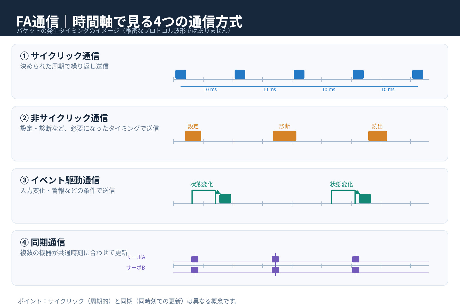
| Communication Method | Description | Typical Use |
|---|---|---|
| Cyclic | Send and receive data at fixed update intervals | Remote I/O and actual values from drives |
| Acyclic | Transfer settings or diagnostic information on request | Parameter changes and fault histories |
| Event-driven | Transmit when a change or alarm occurs | Status change notifications |
| Polling | A master or client queries devices in sequence | Periodic Modbus reads |
| Synchronous communication | Align timing to a shared clock or synchronization event | Multi-axis position and speed synchronization |
| Token passing | Control transmission rights between stations | Access control in FL-net and similar systems |
Cyclic communication and synchronization are different concepts. For example, even if position commands are sent to all servo drives every 4 ms, the drives do not necessarily apply those commands at exactly the same time. Accurate multi-axis synchronization requires checking clock synchronization accuracy, control cycle times, and when receiving devices apply commands.
5. Compatible Devices and Supporting Features: QoS, IGMP Snooping, and PoE
Communication protocols require compatible devices at both ends. Matching Ethernet connectors do not mean that an EtherCAT device can communicate directly with an EtherNet/IP scanner. In addition,QoS, IGMP snooping, and PoE are not types of communication protocol; they are separate features supported by particular devices and switches.
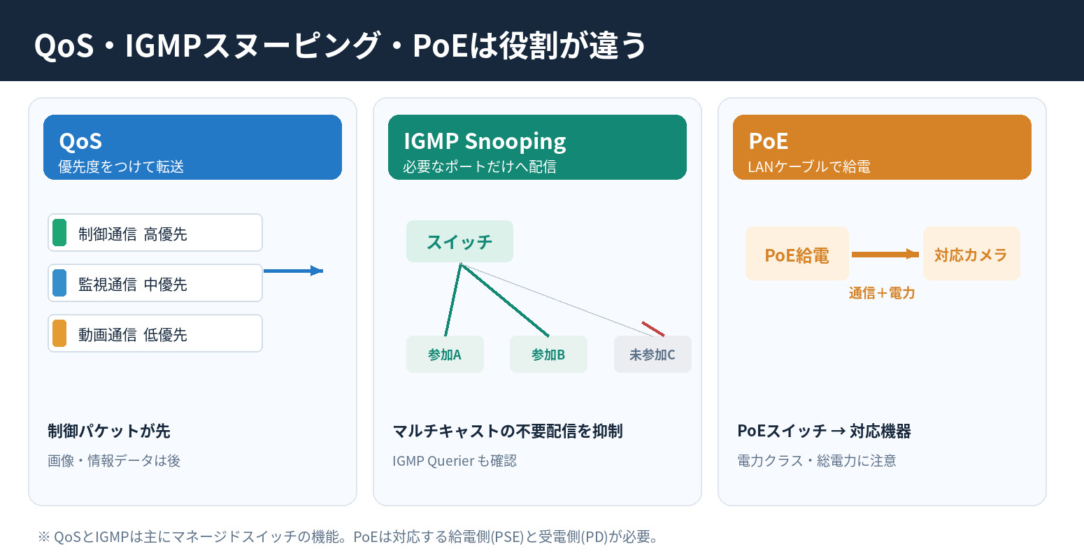
5-1. What Is QoS (Quality of Service)?
QoS classifies network packets and controls transmission queue order and bandwidth according to their priority. For example, when image file transfers and cyclic PLC I/O traffic simultaneously enter a 100 Mbps uplink, a switch’s egress queue may become congested. Giving control packets higher priority can allow them to be forwarded ahead of lower-priority traffic.
Common priority mechanisms include 802.1p/PCP in Ethernet VLAN tags and DSCP in IP packets. However, switches must recognize device-assigned priorities and apply them consistently throughout the network.
Caution: QoS does not increase the available physical bandwidth. When traffic continuously exceeds link capacity, lower-priority packets may be delayed or dropped. Ordinary QoS also does not guarantee strict transmission times; distinguish it from TSN time synchronization and scheduled traffic control.
5-2. What Is IGMP Snooping?
IGMP snooping allows a switch to identify the ports connected to devices that want to receive multicast traffic and forward packets only to those ports. For example, implicit EtherNet/IP communication may use multicast to deliver the same data from one sender to multiple devices.
If IGMP snooping is not functioning, the switch may flood multicast packets to unnecessary ports, adding receive-processing load to unrelated PLCs, HMIs, and other equipment. When configuring multicast, also check the presence and configuration of the IGMP Querier, which is required to manage multicast group membership. On some networks, enabling IGMP snooping without a querier will not provide the expected behavior.
QoS controls which packets receive priority; IGMP snooping controls which ports receive multicast packets. These are separate functions and can be used together. If traffic is unicast-only, IGMP snooping offers no reduction in multicast forwarding.
5-3. What Is PoE (Power over Ethernet)?
PoE is a system that delivers both data and electrical power over compatible Ethernet cabling. The source is called the PSE (Power Sourcing Equipment), and the receiving device is the PD (Powered Device). It can reduce separate power wiring for industrial cameras, wireless access points, and compatible sensors.
| IEEE Standard | Common Name | Maximum PSE Output | Approximate Power Available to PD |
|---|---|---|---|
| 802.3af (Type 1) | PoE | 15.4 W | 12.95 W |
| 802.3at (Type 2) | PoE+ | 30 W | 25.5 W |
| 802.3bt (Type 3) | PoE++ | 60 W | 51 W |
| 802.3bt (Type 4) | 4PPoE, etc. | 90 W | 71.3 W |
Note: The figures represent maximum values for typical IEEE power classes. Actual available power depends on the PD class, cable losses, and the switch’s total power budget.
PoE switches have two constraints: the power available per port and the switch’s total PoE power budget. For example, even if a switch has eight ports rated for 30 W each, it cannot supply 30 W to all eight simultaneously when its total budget is only 120 W. Standard PoE and proprietary power-over-cable technologies such as EtherCAT P use different specifications, so check compatibility. Not every port on an EtherCAT or PROFINET device supports PoE.
5-4. Compatibility Checks Before Connecting Devices
- Do the PLC and connected device implement the same protocol and compatible versions?
- Do they support the required roles, such as Scanner / Adapter, Controller / Device, or Main / Sub?
- Do they implement the necessary functions, such as cyclic I/O, time synchronization, safety communication, diagnostics, multicast, and PoE?
- Are device description files available (such as EtherNet/IP EDS, PROFINET GSDML, EtherCAT ESI, or IO-Link IODD), and are they supported by the configuration software and firmware?
6. Network Design Procedure: Determine Required Speed, Data Volume, and Device Count
In the following example, we consider a system in which one PLC cyclically exchanges data with eight other PLCs. We calculate the RPI, required communication capacity, bandwidth utilization, transmission time, and timeout step by step. The assumptions are for illustration and do not guarantee the performance of any particular product.
Step 1: Define Requirements and Maximum Communication Capacity
| Design Item | Assumed Condition | Meaning |
|---|---|---|
| Network configuration | One central PLC + eight peer PLCs | Nine PLCs in total, with eight communication relationships concentrated at the central PLC |
| Data sent per device | 400 bytes per direction | 400 bytes both from the central PLC to each peer and from each peer to the central PLC |
| Update interval (example RPI) | 4 ms | 250 updates per second |
| Central PLC link speed | 100 Mbps, full duplex | Simultaneous transmission and reception in separate directions |
| Network equipment | Through two managed switches | Actual traffic concentration must be checked for each port |
| Additional function | 100 ms heartbeat | Example of an application-level implementation |
What matters is not just the total number of PLCs, but which PLC communicates with which other PLC, how many bytes it sends, and at what interval in milliseconds. Actual packet counts and congested links differ depending on whether the central PLC communicates separately with all eight peers or uses multicast or shared memory.
Step 2: Calculate the Required Application Data Rate
For application data in one direction, use the following approximation.
Required data rate [bit/s] = Number of PLCs × Data per packet [bytes] × 8 ÷ Update interval [s]
For eight peer PLCs, 400 bytes, and 4 ms (0.004 s):
8 × 400 × 8 ÷ 0.004 = 6,400,000 bit/s = 6.4 Mbps (one direction)
If transmit and receive volumes are equal,the combined bidirectional total is 12.8 Mbps. However, a 100 Mbps full-duplex link has 100 Mbps available in each direction. Do not simply add both directions and divide by 100 Mbps to obtain utilization.
Step 3: Include Packet Headers and Ethernet Overhead
On Ethernet, the link carries not only the data that a PLC wants to send, but also Ethernet, IP, UDP, and application headers, frame-check information, the preamble, and interframe gaps. To simplify the calculation, assume 74 bytes of communication overhead for each 400-byte payload.
| Component Included in Calculation | Assumed Size |
|---|---|
| Application data | 400 byte |
| Ethernet header + FCS | 18 byte |
| IPv4 + UDP headers | 28 byte |
| Higher-layer communication information such as CIP (assumed) | 8 byte |
| Preamble / SFD + interframe gap | 20 byte |
| Total (on-wire occupancy) | 474 bytes per packet |
Important: The 74-byte overhead is an assumption used only in this example. Actual overhead depends on CIP encapsulation, address format, VLAN tags, protocol headers, minimum frame size, and other details. Do not automatically apply these assumptions to EtherCAT, PROFINET, or CC-Link IE TSN. The preamble and interframe gap are not part of the application payload, but they are included because they occupy time on the physical link.
Step 4: Calculate Required Bandwidth and Packets per Second (PPS)
Communication bandwidth [bit/s] = On-wire bytes per packet × 8 × Packets per cycle ÷ Cycle time [s]
If the central PLC sends one packet to each peer PLC:
474 × 8 × 8 ÷ 0.004 = 7,584,000 bit/s = 7.584 Mbps (transmit direction)
The receive direction also requires 7.584 Mbps, resulting in 15.168 Mbps of combined bidirectional traffic. The utilization of the central PLC’s 100 Mbps full-duplex port is 7.584% transmitting and 7.584% receiving.
PPS (transmit) = 8 devices ÷ 0.004 s = 2,000 packets/sPPS (receive) = 2,000 packets/sBidirectional total = 4,000 packets/s
When selecting switches and PLCs, check not only Mbps but also PPS, maximum number of connections, maximum bytes per connection, maximum number of stations, and multicast forwarding performance. With frequent small packets, packet-processing load can become a problem even when the bit rate is relatively low.
Step 5: Configure the RPI (Requested Packet Interval)
RPI is the requested interval between packets, mainly used in implicit I/O communication over EtherNet/IP. For example, an RPI of 4 ms requests data updates every 4 ms for the corresponding connection. RPI does not change the physical 100 Mbps or 1 Gbps link speed. Shortening the RPI increases PPS and bandwidth load.
| RPI (assumed) | One-Way Packets per Second (8 Devices) | Required Transmit Bandwidth | Utilization of 100 Mbps Link |
|---|---|---|---|
| 20 ms | 400 PPS | 1.5168 Mbps | 1.52% |
| 10 ms | 800 PPS | 3.0336 Mbps | 3.03% |
| 4 ms | 2,000 PPS | 7.584 Mbps | 7.58% |
| 2 ms | 4,000 PPS | 15.168 Mbps | 15.17% |
| 1 ms | 8,000 PPS | 30.336 Mbps | 30.34% |
As the table shows, when payload size and number of PLCs are constant,halving the RPI approximately doubles the packet rate and required bandwidth. This assumes that devices support the selected RPI and that PLC task cycles and network configuration can sustain it. With PROFINET, EtherCAT, and CC-Link IE TSN, the corresponding update interval or cycle time is configured under terminology specific to each standard rather than RPI. Modbus is designed around polling intervals and response times.
Step 6: Calculate Actual Transmission Time
First calculate the time needed to place a packet onto the network medium, called serialization time (time required to transmit a frame onto the link).
Serialization time [s] = On-wire data [bytes] × 8 ÷ Link speed [bit/s]
For a 474-byte packet at 100 Mbps:
474 × 8 ÷ 100,000,000 = 0.00003792 s = 37.92 μs
If eight frames arrive simultaneously and must be serialized on the same output link, the transmission time for all eight frames is 8 × 37.92 μs = 303.36 μs. If seven packets are already queued, the eighth may wait up to approximately 265.44 μs before transmission begins (assuming no other traffic).
Furthermore, as an illustrative assumption, suppose the packet traverses three 100 Mbps links and two store-and-forward switches, with 10 μs of processing delay at each switch and 265.44 μs of output-port queueing delay:
Example transmission time ≈ 37.92 × 3 + 10 × 2 + 265.44 = 399.20 μs (about 0.40 ms)
This is a simplified packet-path model for illustration, not a guaranteed upper bound on network latency. Cable propagation delay, other traffic, actual switch forwarding methods, queue scheduling, device-specific communication processing, retransmissions, and errors must be assessed separately.
End-to-end equipment response time must additionally account for sensor response/input filtering, waiting for input acquisition, network transfer, PLC scan and task scheduling, waiting for an output data update, and output-device actuation. An RPI of 4 ms does not mean the output will actuate 4 ms after an input changes.
Step 7: Set Heartbeat and Timeout Monitoring Intervals
A heartbeat is a periodic liveness signal used to confirm that another device is operating. When implementing a separate application-level heartbeat, determine its interval and timeout based on the failure detection time required, temporary communication delays, and acceptable false-alarm risk.
Example: If a heartbeat is sent every 100 ms and a fault is declared after three consecutive missed periods, the design detects a lack of reception roughly 300 ms after the last successful message. A monitoring timeout of 350 ms might be chosen to account for jitter, but the exact detection logic, reference time, and allowed delays must be clearly defined.
For the additional bandwidth in this example, assume a 32-byte heartbeat payload, 74 bytes of communication overhead, eight peer devices, and a 100 ms one-way transmission interval:
8 × (32 + 74) × 8 ÷ 0.1 = 67,840 bit/s = 0.06784 Mbps
Important: EtherNet/IP implicit connections have RPI and connection-timeout mechanisms, so an additional heartbeat is not necessarily required. CIP connection timeouts and safety communication monitoring times vary by device and configuration. Applying a single fixed multiplier to RPI does not work identically for all protocols. Safety-related fault detection also requires suitable safety functions and compliance with applicable safety standards; an ordinary heartbeat alone is insufficient.
Step 8: Verify Headroom and Peak Traffic
Do not finish selecting equipment based only on the calculated average of 7.584 Mbps per direction. Configuration traffic during startup, fault diagnostics, HMI screen reads, file transfers, and bursts concentrated at switches also consume bandwidth. QoS cannot remedy a physical shortage of bandwidth.
For example, if we add an assumed 30% margin to traffic volume, the required bandwidth becomes 7.584 × 1.30 = 9.8592 Mbps per direction . The 30% margin is only an assumption for this calculation, not a universal design rule. Set headroom based on the criticality of the control system, permissible delay, traffic bursts, potential growth in connected devices, and measured values.
7. Practical Protocol Selection Workflow
- Identify connected equipment: Is the connection between PLCs, I/O devices, servo drives, sensors, or higher-level servers?
- Check the installed environment: Determine the communication interfaces of existing PLCs, drives, and I/O devices, and the current network infrastructure.
- Define timing requirements: Determine acceptable input-to-output response time, cycle time, jitter, and synchronization accuracy.
- Define data volume and device count: Estimate bytes, PPS, destination count, and peak simultaneous traffic separately for each direction.
- Check capacity and wiring: Verify the maximum number of devices, cable length, topology, cable type, power delivery, and redundancy.
- Check supporting functions: Review QoS, IGMP snooping, querier, PoE, time synchronization, and safety communication.
- Compare candidates and verify on real equipment: Evaluate achievable cycle time, measured jitter, behavior during faults, maintainability, and implementation cost.
Example Protocol Choices by Application
| Application | Main Candidates | Reason for Selection | Design Considerations |
|---|---|---|---|
| Coordinated operation of multiple PLCs | FL-net, EtherNet/IP, CC-Link IE TSN | Facilitates data sharing between PLCs | Vendor-supported profiles and communication capacity |
| High-speed positioning equipment | EtherCAT, PROFINET IRT, CC-Link IE TSN | Short cycles and synchronization between devices | Synchronization specifications of both drives and controllers |
| Large numbers of distributed I/O devices | EtherNet/IP, PROFINET, CC-Link, EtherCAT | Reduced wiring and cyclic I/O | PPS, update interval, and number of communication partners |
| Advanced sensors | IO-Link | Access to measurements, diagnostics, and parameters | Master-side protocol support and cable length |
| Power meters and temperature controllers | Modbus RTU / TCP | Register access and ease of implementation | Polling cycle, number of devices, and response time |
| Partial modernization of existing equipment | Existing CC-Link, DeviceNet, PROFIBUS, etc. | Easier reuse of peripheral devices | Product availability, compatibility, and long-term maintenance |
8. Common Design Problems and Their Solutions
Data Is Delayed Despite Adequate Communication Bandwidth
Even with low average Mbps, simultaneous transmissions from several devices can concentrate frames at a switch’s output port. Check PPS, utilization per port, queue drops, PLC task cycles, and RPI settings. Investigate peak traffic, not just averages.
Multicast Traffic Is Being Sent to Every Port
When multicast is used, check IGMP snooping, the querier, and multicast group membership. Proper configuration may reduce flooding to devices that do not need the traffic.
A Camera Reboots Even Though the Switch Supports PoE
In addition to per-port PoE ratings, investigate the switch’s total power budget, the device’s peak power consumption, voltage drop over long cables, ambient temperature, and available power supply headroom.
Ethernet Devices from Different Manufacturers Cannot Communicate
Devices may use the same RJ-45 connector but different higher-layer protocols. Compare supported standards, device roles, description files, and software versions. Use a gateway or compatible I/O master if necessary.
An Ordinary Communication Heartbeat Is Being Used in Place of an Emergency Stop
General network monitoring cannot replace a safety function. Design the system around a safety PLC, suitable safety communication (such as CIP Safety, PROFIsafe, or FSoE), and a machine-safety risk assessment.
This book provides a particularly clear explanation: Fully Illustrated in Color: Understanding Sequence Control from the Fundamentals
9. Frequently Asked Questions (FAQ)
Q1. Can EtherNet/IP and EtherCAT devices communicate directly because both use Ethernet?
A. In principle, they cannot communicate directly without additional support. Although both use Ethernet at the physical layer, their communication methods differ. A gateway, compatible master, or multiprotocol device supporting both standards is required.
Q2. Does reducing RPI always improve PLC response speed?
A. Not necessarily. Although the communication update interval becomes shorter, PLC scan or task cycles, communication-processing load, or update processing in the other device may become the bottleneck. An excessively short interval may increase network load and timeouts.
Q3. Does configuring QoS eliminate the need for bandwidth design?
A. No. Bandwidth planning is still required. QoS prioritizes traffic during congestion; it cannot increase the physical capacity of a 100 Mbps link.
Q4. Which should be configured first: IGMP snooping or QoS?
A. It depends on the communication method and the problem being addressed. Use IGMP snooping to reduce unnecessary multicast forwarding and QoS to address contention in transmission queues. On networks using multicast, verifying the querier is also important.
Q5. Can any industrial Ethernet device receive power through a PoE-capable LAN cable?
A. No. Both the power-sourcing and powered devices must support compatible PoE standards. Do not inject power into unsupported ports. EtherCAT P also uses a different method from standard PoE.
Q6. Does Modbus TCP use cyclic communication?
A. It normally uses request-response communication. A client can retrieve data periodically by sending read requests at fixed intervals, but this operates differently from EtherNet/IP’s RPI mechanism.
Q7. How many milliseconds does it take to transmit 400 bytes over 100 Mbps?
A. The payload alone takes 32 μs. 400 × 8 ÷ 100,000,000 = 32 μs. However, headers and other overhead must also be transmitted. Under this article’s assumptions, 474 bytes take 37.92 μs. Actual response time must also account for queues, switches, PLC processing, and other delays.
Q8. Which communication standard is most recommended for a new FA system?
A. It depends on the PLC used and the required performance. Candidates include EtherCAT for multi-axis synchronization, EtherNet/IP or PROFINET for PLCs and general I/O, and IO-Link for sensor diagnostics and configuration. Compare device compatibility, maintainability, and response time.
10. Summary: Communication Standards Cannot Be Selected by Speed Alone
- Network levels (controller / field / sensor) and communication methods (cyclic / acyclic / synchronous) are different classifications.
- Compare conventional standards such as CC-Link, DeviceNet, PROFIBUS, and FL-net with industrial Ethernet standards such as EtherCAT, PROFINET, CC-Link IE TSN, and EtherNet/IP according to the application.
- Shortening EtherNet/IP’s RPI increases update frequency, PPS, and bandwidth requirements. Check the corresponding cycle settings for other protocols.
- QoS controls packet priority, IGMP snooping directs multicast forwarding, and PoE supplies power over LAN cabling. Each serves a different purpose.
- Design maximum data capacity, link speed, PLC count, PPS, congestion on individual links, transmission time, and timeouts as an integrated system.
- Do not stop at calculated figures; verify actual jitter, behavior during communication failures, and safety on real equipment.
For your next network design task, start by creating a communication matrix showing which devices communicate with each other, how many bytes they exchange, and how often in milliseconds. This makes equipment selection easier and helps prevent communication problems.
References and Primary Sources
- CC-Link Partner Association: Network Specifications (CC-Link, CC-Link/LT, etc.)
- CC-Link Partner Association: Features of CC-Link IE TSN
- Japan Electrical Manufacturers’ Association (JEMA): FL-net Standards and Technical Resources
- ODVA: EtherNet/IP
- ODVA: Securing EtherNet/IP Networks (QoS and IGMP Explanation)
- EtherCAT Technology Group: How EtherCAT Works
- Siemens: Differences Between PROFINET RT and IRT
- Modbus Organization: Modbus Specifications
- OMRON: CompoNet Master Specifications
- Siemens: Overview of IO-Link Communications
- Cisco: Industrial PoE Standards and Power Levels
Technical specifications refer to association and manufacturer publications available as of October 2026. Standards can be revised, and product-specific specifications and firmware limitations may apply. Confirm the latest manual for the selected device model before finalizing a design.