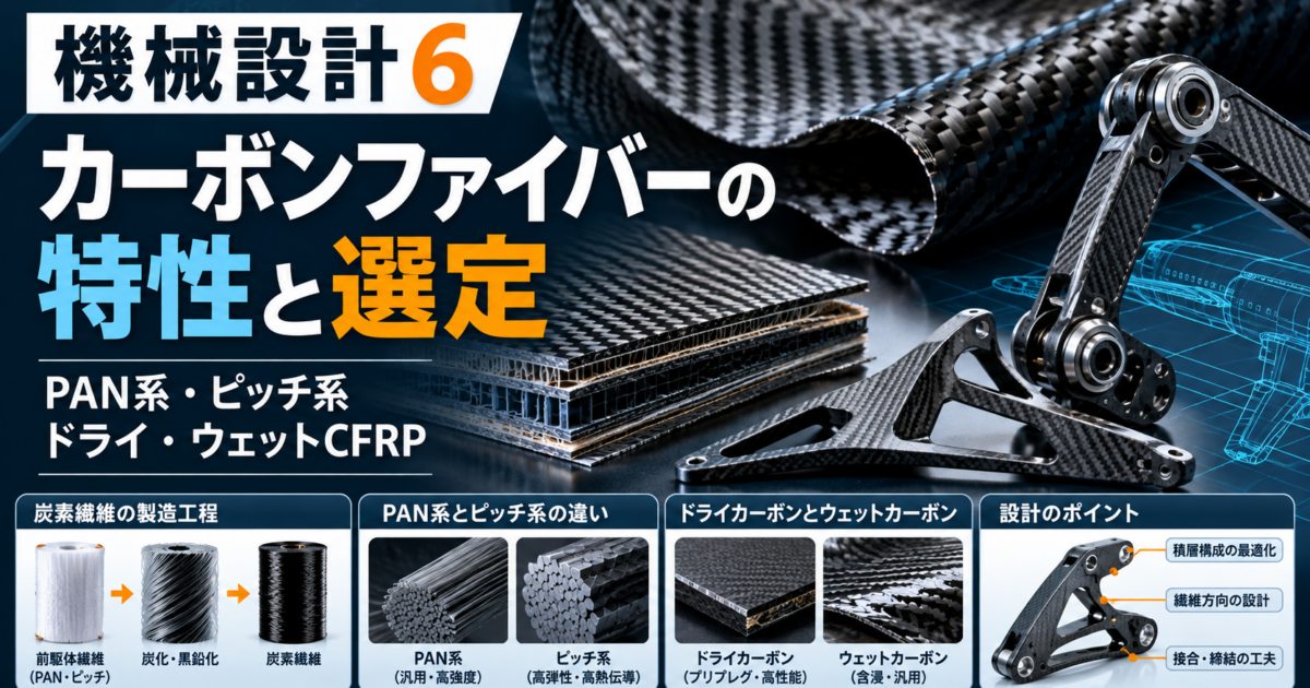
Have you ever heard that “carbon fiber is stronger and lighter than steel”? In actual mechanical components, carbon fiber (on its own) and CFRP (carbon fiber-reinforced plastic) are different materials, and their performance varies significantly depending on the fiber orientation, resin, laminate structure, and molding quality . In this article, we’ll compare PAN-based and pitch-based carbon fibers, dry carbon and wet carbon, the manufacturing process of carbon fiber itself, JIS standards, and design and machining considerations—all presented in a format useful for mechanical design.
Introduction | What Is Carbon Fiber? Differences from Steel, Aluminum, and Titanium
Distinguishing Between Carbon Fiber Itself and CFRP
Carbon fiber (CF) is an extremely fine fiber composed primarily of carbon. CFRP (Carbon Fiber Reinforced Plastics) is created by embedding these fibers—which serve as reinforcing material—in resin. Typically, finished structural components such as plates, brackets, and pipes are made of CFRP. The tensile strength of the fiber alone cannot be directly applied as the strength of the finished component.
While metals can often be approximated as homogeneous and isotropic in many designs, anisotropy is a key characteristic of CFRP. Even if it is strong in the longitudinal 0° direction, it exhibits different strengths and stiffness in the perpendicular 90° direction or in the direction of the layer thickness. A major feature of CFRP is that it involves not only “selecting the material before determining the shape,” but also “designing the internal laminate structure to match the load direction.”
| Material | Approximate Density (g/cm³) | Main Advantages | Main Considerations |
|---|---|---|---|
| CFRP (Carbon Fiber + Resin) | Approx. 1.4–1.7 | Lightweight; can be designed for high specific strength and high specific stiffness in the load direction | Anisotropy, impact, delamination, fastening, cost |
| Carbon Fiber Alone | Approx. 1.7–2.2 (depending on fiber type) | High tensile strength and modulus of elasticity in the fiber axis direction | Fiber bundle values cannot be used as guaranteed values for the finished CFRP |
| Aluminum Alloy | Approx. 2.7 | Lightweight; proven track record in machining, thermal conductivity, and recycling | Stiffness, surface damage, corrosive environments |
| Titanium alloy | Approx. 4.4–4.5 | High specific strength, corrosion resistance | Expensive, machinability, galling in sliding parts |
| Mild steel | Approx. 7.85 | High rigidity, low cost, fastening and welding track record | Weight, rust prevention |
What kinds of products are they used in?
It is used in aerospace equipment, industrial robot arms, material handling mechanisms, support members for inspection and measurement equipment, drones, bicycles and sporting goods, and as reinforcement layers for pressure vessels. The requirements extend beyond light weight to include reduced inertia, deflection control, dimensional stability, and fatigue resistance.
Chemical and Physical Properties | Density, Electrical, Thermal, and Corrosion Resistance
Weight and Specific Strength | Even Though It’s Lightweight, Don’t Compare Based Solely on “Volume”
The density of CFRP is approximately 1.4–1.7 g/cm³ for typical resin-based structural laminates. This is lower than that of steel (7.85 g/cm³) and aluminum alloys (2.7 g/cm³), and as a general rule, CFRP has a mass of about 18–22% that of steel for the same volume. However, since the plate thickness, reinforcement areas, and joint configurations vary to meet the same load, stiffness, and durability requirements, the final part’s mass cannot be determined by simple specific gravity calculations alone.
Electrical Conductivity | Directions of Conductivity and Areas Requiring Insulation
Carbon fibers are electrically conductive. The electrical conductivity of CFRP varies significantly depending on the fiber orientation, contact between fibers, resin type, and lamination direction; in some cases, current flows more easily along the fiber direction than through the thickness. Assuming it is an electrical insulator can lead to problems such as short circuits, sensor errors, and issues with grounding and shielding designs. When used in electronic devices, the finished product must be evaluated for resistance, insulation, and electromagnetic compatibility.
Thermal Conductivity | Significant Differences Between PAN-Based and Pitch-Based Types
The thermal conductivity of carbon fiber varies widely depending on the product. In particular, highly oriented mesophase pitch-based carbon fiber is a material that readily achieves high thermal conductivity and high elastic modulus in the fiber axis direction. The thermal conductivity of finished CFRP varies in the fiber direction, the orthogonal direction, and the thickness direction, and depends on the combination of resin and fibers. When selecting a material for heat dissipation, use the direction-specific measured values for the laminate rather than the manufacturer’s published values for individual fibers.
Thermal Expansion and Heat Resistance | Fibers Have High Heat Resistance, but Resins Do Not
Carbon fibers have low thermal expansion in the axial direction, and depending on the grade, may even exhibit negative values. Since the thermal expansion of CFRP laminates is influenced by fiber orientation and the resin, calculations must be performed for each component orientation. While carbon fibers themselves exhibit excellent high-temperature stability, the operating temperature range of resin-based CFRP is limited by the resin’s glass transition temperature (Tg), thermal degradation, and load and service life. Just because a part is made of carbon fiber does not mean resin-based components can be used at high temperatures without restriction.
Chemical Properties and Corrosion | Problems Can Arise Even If the Fibers Themselves Do Not Rust
Although carbon fibers do not develop red rust like iron does, care must be taken regarding resin moisture absorption, chemical degradation, UV degradation, and changes at the adhesive interface. CFRP behaves as a relatively “noble” material electrically, and when it conducts electricity through an electrolyte in contact with metals such as aluminum, it may promote galvanic corrosion of the other metal. Insulation should be provided using a glass fiber layer, sealant, insulating washers, or appropriate surface treatment.
Mechanical Properties | Strength, Stiffness, Toughness, Processability, Price
Strength and Stiffness | Do Not Confuse Fiber Values with Laminate Values
Among high-strength carbon fiber products, there are those with tensile strengths in the GPa range and tensile moduli of approximately 200–300 GPa. Some high-modulus types have even higher tensile moduli. However, these are evaluated values for single fibers or resin-impregnated yarns in the fiber axis direction. Even in UD (Unidirectional) CFRP, the strength and modulus in the 0° direction vary depending on the resin, fiber content, porosity, curing, and defects, and are generally lower in the 90° direction and in the interlaminar direction.
To estimate stiffness, use direction-specific values such as E₁, E₂, G₁₂, and Poisson’s ratio ν₁₂. It is incorrect to design parts by directly comparing the Young’s modulus of steel (200 GPa) with that of a single carbon fiber (200 GPa) . Please use the allowable values for the specific prepreg and laminate configuration being used.
Toughness, Ductility, and Impact | CFRP Fails Differently from Metals
Most CFRP materials do not exhibit significant plastic deformation like metals; instead, they fail due to fiber breakage, resin cracking, or interlaminar delamination. Even without significant surface deformation, interlaminar delamination can occur internally due to drops or impacts. Considering post-impact compressive strength (CAI) and ultrasonic testing, damage-tolerant design is crucial for components requiring personnel protection and long-term reliability.
Fatigue and Vibration | A Strength, but Not a Panacea
CFRP can be expected to exhibit high fatigue performance when loads are applied in the appropriate direction, and reducing the weight of moving parts also leads to a reduction in inertial forces. However, damage may progress due to interlaminar shear, localized compression around holes, adhesive delamination, or repeated temperature and humidity changes. Design criteria should include stiffness reduction, natural frequency, and fatigue cycles.
Formability, Machinability, Cost, and Recyclability
CFRP is a manufacturing technology that encompasses materials, lamination, molding, and post-processing. For prototyping, options include hand lay-up and machining from pre-made laminates; for mass production, RTM, pressing, and automated lamination are also viable candidates. Generally, the unit cost is higher than that of general-purpose steel or aluminum, and additional costs are incurred for prepreg storage, molds, curing, non-destructive testing, and hole drilling. With thermosetting CFRP, separating and recovering the resin and fibers is difficult, and regenerated fibers obtained through thermal decomposition may exhibit changes in performance, length, and applications. On the other hand, thermoplastic CFRP offers options for remolding and reuse, so component design and recovery methods are considered together.
Here is an easy-to-understand book. “The ‘Know-It-All’ Series: A Thoroughly Easy-to-Understand Book on Carbon Fiber”
Differences Between PAN-Based and Pitch-Based CFRP | Raw Materials and Properties
PAN-Based | The Mainstream High-Strength Type
PAN-based carbon fiber is produced by flame-retardant treatment and carbonization of polyacrylonitrile (PAN) fibers as a precursor. Due to its balance of high strength, high specific strength, and practicality, it is widely used in structural components for aircraft, automobiles, sporting goods, and general industry. PAN-based carbon fibers come in various grades, including standard modulus, medium modulus, and high modulus.
Pitch-Based Carbon Fibers | An Option for High Rigidity and High Thermal Conductivity
Pitch-based carbon fibers use petroleum- or coal-derived pitch as their raw material, and their properties vary significantly depending on the type, such as optically isotropic pitch and mesophase (anisotropic) pitch. Not all pitch-based materials have high elastic modulus. Highly oriented mesophase pitch-based materials include products that exhibit extremely high elastic modulus and thermal conductivity in the fiber axis direction, and are used in precision instruments, satellites, robotic structures, and high-thermal-conductivity components. When designing, it is important to evaluate the trade-offs between strength reduction and damage tolerance.
| Comparison | PAN-based (Typical structural applications) | Pitch-based |
|---|---|---|
| Precursors | Polyacrylonitrile-based fibers | Petroleum and coal pitch-based fibers |
| Key strengths | High tensile strength and high specific strength, Track Record of Adoption | High modulus of elasticity and high thermal conductivity in highly oriented types |
| Modulus of Elasticity Trends | Wide variety ranging from standard to high-modulus products | Extremely wide range from low to ultra-high modulus |
| Applications | Aerospace and industrial components, sports, pressure vessels | satellites, precision structures, thermal management, etc. |
| Points to Note | Fiber orientation, resin, and laminate design | Brittleness, cost, and availability of high-modulus products |
Manufacturing Process for Carbon Fiber (Pure Fiber) | PAN-Based and Pitch-Based
This section introducesthe process for manufacturing carbon fiber itself, which is distinct from the “dry/wet” processes used to mold CFRP using that fiber. Tensile strength and modulus of elasticity are tailored by adjusting temperature, tension, residence time, and surface treatment.
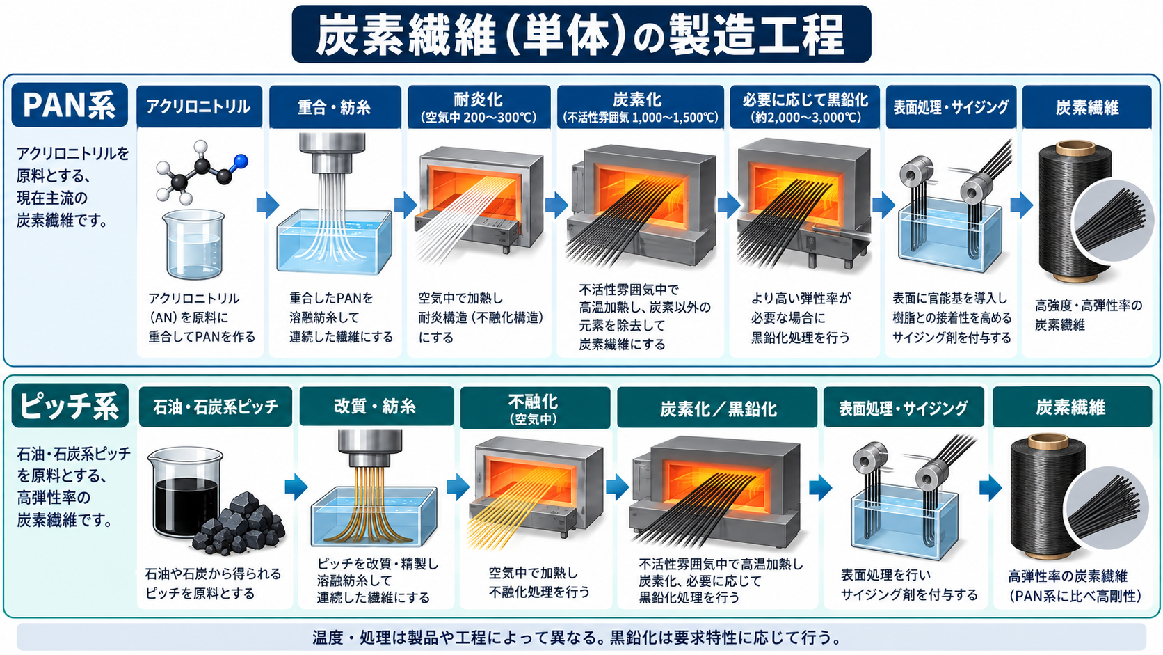
PAN-based process: Polymerization → Spinning → Flame retardancy treatment → Carbonization → Surface treatment
- ① Polymerization and Spinning: PAN precursor fibers are produced from a polymer primarily composed of acrylonitrile.
- ② Flame Retardant Treatment (approx. 200–300°C, in air): The fibers undergo oxidation and cyclization, transforming them into a structure that does not melt even during subsequent high-temperature processing.
- ③ Carbonization (typical example: approx. 1,000–1,500°C, inert atmosphere): Elements other than carbon are removed to form the carbon fiber structure.
- ④ Graphitization (if necessary; high-temperature treatment, approx. 2,000–3,000°C): Further heat treatment is performed depending on the desired properties, such as high elastic modulus.
- ⑤ Surface treatment and sizing: Adhesion to the resin and handling properties are optimized, and the fiber bundles are wound into a tow.
Pitch-based Process: Raw Material Preparation → Melt Spinning → Non-melting Treatment → Carbonization and Graphitization
- ① Modification and Refining of Raw Pitch: Pitch suitable for the intended purpose is obtained from heavy petroleum or coal-based fractions. In some cases, mesophase conversion is performed.
- ② Melt spinning: Pitch at the appropriate viscosity and temperature is drawn into fine fibers.
- ③ Non-melting treatment: Stabilize the material so that it does not melt even when heated.
- ④ Carbonization and graphitization as required: Process in an inert atmosphere to form the required carbon structure and crystalline orientation.
- ⑤ Surface Treatment and Sizing: Prepare the fibers for subsequent resin impregnation and processing.
Key Points for Designers: Do not assume that “PAN-based fibers are necessarily high-strength” or “pitch-based fibers are necessarily high-stiffness”; instead, select fibers based on the fiber manufacturer’s product-specific data and measured values after the composite has been fabricated.
How to Read Standards | JIS, Material Specifications, and Test Methods
Structure of JIS Numbers | Material Names and Test Standards Are Separate
JIS standards are denoted as “JIS + field code + standard number + year of edition (if applicable).” The “K” category covers standards related to resins and plastics in the chemical field, while the “R” category covers standards in the ceramics field, among others. Unlike steel (e.g., SS400), the final performance of CFRP is not determined by a single general material symbol alone. For CFRP, specifications are defined by a combination of fiber products, resin, laminate specifications, curing conditions, test methods, and allowable values.
Representative Test Standards for Designers to Refer To
| Standard Number | Scope | Intended Use in Design |
|---|---|---|
| JIS R 7606 | Tensile Properties of Individual Carbon Fibers | Evaluation of the Carbon Fiber Itself |
| JIS R 7608 | Tensile properties of resin-impregnated yarn | Evaluation of tensile strength and modulus of elasticity of fiber bundles |
| JIS K 7074 | Bending test for CFRP | Bending Properties of Laminates |
| JIS K 7075 | Fiber Content and Void Fraction of CFRP | Molding Quality Control |
| JIS K 7076 | Testing the Compressive Properties of CFRP | Compressive Strength and Design Verification |
| JIS K 7078 | Interlaminar Shear Test for CFRP | Interlaminar Quality and Apparent Interlaminar Shear Strength |
| JIS K 7089 | Post-Impact Compression Test for CFRP | Evaluation of damage tolerance |
| JIS K 7164 | Tensile properties of isotropic and orthotropic fiber-reinforced plastics | Tensile performance of laminated plates |
Specifications in Drawings | “CFRP” Alone Is Insufficient
- Carbon fiber manufacturer and product grade (PAN-based/pitch-based, tow count, UD, woven fabric, etc.).
- Resin type (epoxy, PEEK, etc.), glass transition temperature (Tg), and environmental resistance specifications.
- Lamination direction and sequence, number of plies, nominal thickness of each layer, allowable panel thickness, and fiber volume fraction (Vf).
- Molding method, curing cycle, defoaming and void criteria, and finishing and bonding specifications.
- Holes, end faces, inserts, and joints; dimensions and geometric tolerances; inspection methods and acceptable defects.
- Mechanical property test methods; test temperature and humidity; test specimen orientation and sampling locations; traceability.
Differences in Manufacturing Methods | Dry Carbon vs. Wet Carbon
Dry Carbon | Generally refers to prepreg laminate molding
In the Japanese market for automotive and exterior parts, “dry carbon” typically refers to CFRP products made by cutting and laminating prepregs that have been pre-impregnated with resin, and then curing them in an autoclave, furnace, or mold using a vacuum bag. It allows for easy control of fiber content, resin content, layup direction, and curing conditions, making it suitable for applications requiring high specific strength and high specific stiffness. On the other hand, prepregs require careful management of storage temperature, shelf life, material costs, and equipment costs.
Wet Carbon | Generally refers to manual resin impregnation molding
“Wet carbon” generally refers to products made by placing dry carbon fiber cloth into a mold, impregnating it with liquid resin via hand lay-up, de-aerating it with a roller, and then curing it. It requires relatively little equipment investment and is suitable for prototyping and small-batch production of covers and exterior parts. Depending on working conditions, variations may occur in resin content, air bubbles and voids, as well as dimensions and strength. These issues can be mitigated through the use of vacuum bags and process control.
Note on Terminology: “Dry” may sometimes refer to a material state meaning “resin-free,” while “wet” may mean “resin-containing”; terminology is not standardized within the industry. Furthermore, “dry carbon” does not necessarily mean autoclave-cured, nor does “wet carbon” necessarily mean low strength. Strength is determined by the fibers, resin, layup, porosity, curing, and inspection.
| Perspective | Dry Carbon (Conventional Prepreg Molding) | Wet Carbon (Conventional Hand Layup) |
|---|---|---|
| Material Preparation | Pre-impregnated prepreg | Impregnating dry fabric or fibers with liquid resin |
| Resin Quantity Control | Relatively easy to control | Depends on the work process and degassing steps |
| Equipment and Cost | Refrigerated storage/ refrigerated/frozen storage and furnaces, which can be costly | Easy to start with simple equipment |
| Molding and Quality | Reproducibility is easily achieved under controlled conditions | Quality variations are prone to occur due to skill levels and process control |
| Main Applications | High-performance structural components, precision applications | Prototyping, exterior trim, covers, small-batch production |
| Points to Note | Shelf life, curing, equipment constraints | Excess resin, voids, finish inconsistencies |
Other Manufacturing Methods | RTM, VaRTM, Filament Winding, Thermoplastic CFRP
RTM (Resin Transfer Molding) is a method in which resin is injected into fibers placed in a closed mold, while VaRTM (Vacuum Infusion) is a method that utilizes vacuum. Filament winding involves winding fiber bundles around a mandrel to create pressure vessels and cylindrical structures. For thermoplastic CFRP, it may be possible to choose between molding via heating and pressing or fusion bonding. We will compare these methods in terms of mass production, geometry, mechanical properties, and mold costs.
Differences in Fiber Configuration | UD Materials, Woven Fabrics, and Short-Fiber CFRP
UD (unidirectional) materials allow fibers to be efficiently aligned in the direction of the principal load. Woven fabrics (such as plain weave and twill weave) have fibers in both the longitudinal and transverse directions; however, the undulation of the weave may affect performance. While short-fiber CFRP facilitates mass production of complex shapes via injection molding, it does not necessarily achieve the same high directional strength as continuous-fiber laminates. The internal laminate configuration cannot be determined solely by the surface weave pattern.
How to Select? | Design Methods and Tips by Application
Step 1: Determine Whether CFRP Is Truly Necessary
① Weight reduction (inertia of moving parts) ② Required stiffness and natural frequency ③ Static loads, fatigue, and impact ④ Temperature, humidity, and chemical exposure ⑤ Production volume, delivery time, and maintainability ⑥ Joining methods and quality assurance ⑦ Total cost. When the benefits of weight reduction—such as reduced load on servo motors or increased speed—are significant, the advantages of using CFRP can be quantitatively evaluated.
Step 2: Align the fiber orientation (0°, 90°, ±45°) with the applied load
| Fiber Orientation | Main Role (Guideline) | Design Examples |
|---|---|---|
| 0° | Shares the primary tensile and bending loads in the longitudinal direction | Long arms, beams, tensile members |
| 90° | Suppresses transverse and circumferential loads and cracking | Circumferential reinforcement for panels and tubes |
| +45°/ −45° | Distributes shear and torsional loads | Rotating shafts, box-shaped structures, and around joints |
| Multidirectional/Balanced Lamination | Handles loads in multiple directions and controls coupling between laminates | Enclosures and brackets subjected to complex external forces |
As an example, [0/+45/90/−45]s illustrates an approach to symmetrical lamination in multiple directions. The “s” at the end indicates that the laminate is symmetrical with respect to the center plane of the sheet thickness. However, this is an illustrative lamination example and does not constitute recommended specifications or guaranteed strength for specific parts. The ply orientation, number of plies, sequence, symmetry, and balance at ±45° should be evaluated based on the actual load.
Step 3: Design Holes, Bolts, and Inserts as “Weak Points”
CFRP may be vulnerable to surface pressure around holes, notches, and interlaminar delamination. In areas subject to concentrated loads, consider using metal bushings, inserts, enlarging the seating surface area, applying localized reinforcement plies, or combining adhesive bonding with fastening. Since tightening with the same torque as for metal can cause the clamping force to vary due to localized damage or creep, verify tightening control, repeated tightening, temperature and humidity conditions, and intermetallic corrosion.
Step 4: Handling Edge Surfaces, Curvature, and Wall Thickness Variations
Sharp internal angles, abrupt changes in the number of plies, and sharp bends can cause fiber wrinkling, voids, stress concentration, and delamination. We consider appropriate radii of curvature, gradual ply reduction, load paths that minimize fiber breakage, and sandwich structures, and protect end faces with resin or paint. The required dimensions are determined based on the selected prepreg thickness, molding method, and quality control capabilities.
Step 5: Precautions for Cutting and Drilling | Dust, Delamination, and Tool Wear
Since CFRP fibers are stiff and the resin is susceptible to heat damage, drilling and trimming can cause fiber fraying, delamination at the exit, burrs, tool wear, and heat damage. Select CFRP-specific drills, diamond-based tools, appropriate cutting conditions, backing material, secure clamping, and adequate dust collection. Since machinability varies depending on fiber orientation, inspect not only the hole diameter but also the end face and internal damage.
Carbon fiber dust can irritate the skin, eyes, and respiratory system, and if conductive dust enters electrical equipment, there is a risk of malfunction or short circuits. Use local exhaust ventilation, suitable dust collection systems, safety goggles, gloves, protective clothing, respiratory protection, and electrical protection for equipment based on a risk assessment. Handle resins and solvents in accordance with the SDS and the equipment manufacturer’s safety procedures.
Step 6: Inspection | Preparing for Hidden Damage
Even if the appearance is normal, voids or delamination may remain. Depending on design requirements, consider methods such as visual and dimensional inspection, ultrasonic testing, X-ray CT, tap testing, fiber content and porosity analysis, and destructive testing. For critical components, it is important to clearly specify acceptable defects and inspection scope in the procurement specifications and not to judge quality based on visual inspection alone.
Specific Examples from Design Sites | Which Material to Choose?
| Components and Requirements | Top Candidate | Reasons for Selection and Considerations |
|---|---|---|
| Long Arm for High-Speed Transport Robot | PAN-based UD CFRP Laminated Pipe / Metal + CFRP | Weight reduction and reduced inertia. Evaluate 0° bending, ±45° torsion, and joint performance |
| Support beams for precision measuring instruments | Consider high-modulus CFRP or pitch-based fibers | Reduce deflection and thermal deformation. Balancing high rigidity and damage tolerance |
| Housings for drones and mobile equipment | CFRP / Aluminum alloy | Weight reduction is advantageous. However, compare impact resistance, EMC, and repairability |
| Exteriors, covers, and prototype panels | Wet lay-up / Pre-fabricated CFRP sheets / aluminum | Prioritize processing costs, appearance, and impact resistance for small production runs |
| Hollow shafts subjected to bending and torsion | Directionally laminated CFRP / alloy steel | Design for torsional stiffness and connections with bearings and couplings |
| High-temperature, high-friction sliding parts | Steel, ceramics, etc. | Consider the Tg, wear, and contact pressure of resin-based CFRP |
| Screw-type fixtures subject to repeated attachment and removal | Aluminum, steel, CFRP + metal inserts | Compare screw durability, fastening management, and procurement costs |
This book is also easy to understand. Machining of CFRP (Carbon Fiber-Reinforced Plastic)
Mini Example of Design Calculations | Comparing Tension Rods with the Same Cross-sectional Area
Consider a member 1 m long with a cross-sectional area of 100 mm²: the mass is approximately 0.16 kg for CFRP with a density of 1.6 g/cm³, and approximately 0.785 kg for steel with a density of 7.85 g/cm³. However, for the elongation ΔL=FL/(AE), the value of E must be the “effective elastic modulus in the load direction of that CFRP laminated member.” Even if a component of the same shape is approximately 80% lighter, there is no guarantee that it will meet requirements for stiffness, buckling, and joint strength.
Frequently Asked Questions (FAQ)
Are carbon fiber and CFRP the same thing?
No, they are not the same. Carbon fiber refers to the carbon fibers themselves, while CFRP is a composite material made by bonding carbon fibers with resin. Performance as a structural component is determined by the lamination method, resin, and manufacturing quality.
Is dry carbon always stronger than wet carbon?
Not necessarily. Dry molding using prepregs tends to make it easier to control resin content and the manufacturing process, but performance varies depending on fiber grade, lamination sequence, voids, and curing conditions. Comparisons should be made based on the guaranteed values of the finished product and the test conditions.
What is the difference between PAN-based and pitch-based carbon fiber?
High-strength PAN-based carbon fiber is widely used for structural applications, while pitch-based carbon fiber—particularly the mesophase type—offers high elastic modulus and high thermal conductivity. However, both series include multiple varieties, so strength and stiffness cannot be determined based on raw material classification alone.
Why are 0°, 90°, and ±45° orientations necessary for CFRP?
This is because the material tends to bear forces more easily in the direction the fibers are oriented. The 0° orientation handles loads along the main axis, 90° handles lateral loads, and ±45° handles shear and torsional loads. The required number of plies and their sequence are determined based on the actual load conditions.
Is CFRP absolutely lighter and stronger than metal?
While it excels in weight reduction, its relative advantages and disadvantages vary depending on orientation-dependent property differences, as well as compression, impact resistance, joining methods, and processing costs. Please compare the performance of the finished parts rather than relying solely on the strength of the material itself.
Can ordinary metal drills be used to drill holes in CFRP?
It depends on the material, hole diameter, tolerances, and required strength, but generally, tools and conditions designed for CFRP are most suitable. Since fiber fraying, delamination, dust generation, and tool wear can be issues, machining and quality control must be tailored to the specific part requirements.
Summary | Selecting Carbon Fiber Involves “Fiber + Resin + Laminate + Process”
Unlike metal, CFRP offers the significant advantage that its internal strength and stiffness can be designed to align with the load direction. After distinguishing between PAN-based and pitch-based fibers, as well as between individual fibers and CFRP, and between dry and wet processes, design the entire system—from fiber orientation, resin, and layup sequence to fastening, machining safety, and quality inspection—as an integrated whole.
Reference Materials & Related Articles
- Carbon Fiber Association | How Carbon Fiber Is Made (PAN-based and Pitch-based Processes)
- Carbon Fiber Association | Types of Carbon Fiber (Classification by Type and Modulus of Elasticity)
- Mitsubishi Chemical | Carbon Fiber Manufacturing Methods
- Japan Industrial Standards Committee (JISC) (Current JIS Search)
- TWI | Composite Manufacturing Methods (wet lay-up, prepreg, RTM, etc.)
- Monash University | Safety Management of Carbon Fiber Composites
- Mechanical Design 1 | Properties and Selection of Aluminum Alloys
- Mechanical Design 2 | Properties and Selection of Copper and Copper Alloy Properties and Selection
- Mechanical Design 3 | Iron and Iron Alloy Properties and Selection
- Mechanical Design 4 | Properties and Selection of Titanium and Titanium Alloys
- Mechanical Design 5 | Properties and Selection of Magnesium Alloys(Please check the publication status)
The figures in this article are representative values intended for introductory purposes. Please prioritize product-specific specifications, operating environments, material testing, the latest JIS standards, design tolerances, manufacturing processes, and safety procedures. For structural components, layered analysis, quality assurance, and actual equipment testing are required.