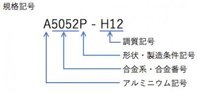
Do not know as it is known, how to select power supply and circuit breaker
Selection of power supply is the foundation of equipment and equipment.
Depending on this selection, the countries, areas of use, and methods of use are largely restricted.
Therefore, let’s think first.
The power supply here is a low voltage (AC 1000 V or less) talk.
Especially it is the selection method for equipment and equipment.
I would like to talk about power selection (AC) and selection of circuit breakers.
Power Supply Selection
First of all I would like to select the power supply.
We will select power supply for equipment and equipment as we select power supply.
There is a necessity of choosing the power source mainly depending on the place, type and usage to use
.
Flow in power selection
2. Power supply stability
3. Selection of commercial voltage (single phase, three phase) to be used
4. Selection of equipment to be used
Depending on the equipment used, 3 and 4 may be reversed.
If you want to use it in various areas, if the power supply and the used power supply which are absolutely supplied as applications are different, you can also change it with a transformer etc, so please take it into consideration.
Verify the voltage of the area mainly used
This is not the case when the power supply is other than the commercial power supply, but check the voltage of the main use area of equipment and equipment to be designed from now.
The table below shows typical commercial power supply voltage.
However, voltages other than this table may be available.
Please use it for reference level.
Regional Commercial Supply Voltage (AC)
| Region | Household (single phase) | Industrial (three phase) | frequency |
|---|---|---|---|
| Japan | 100 V | 200 V | 50/60 Hz |
| America | 115 V | 230 V | 60 Hz |
| UK | 230 V | 400 V | 50 Hz |
| Germany | 230 V | 400 V | 50 Hz |
| China | 220 V | 380 V | 50 Hz |
| India | 220 V | 380 V | 50 Hz |
| Thai | 230 V | 400 V | 50 Hz |
| Australia | 240 V | 415 V | 50 Hz |
Commercial voltage and frequency vary depending on the area.
Let’s check the supplied power supply of the area to be used and design it.
Also, if you are considering power generation from self-power generation or batteries, let’s check the power specifications there.
Voltage and frequency are different depending on the area. Confirm specification of power supply side
Power supply stability
Japan maintains a very good power supply stability.
However, there are many places where power supply stability is not good depending on the region.
As far as know, there is also a region that once the entire region in a few months may become a sudden power outage.
It also causes shortening of the life of the equipment.
Let’s got the information by the measurement and interviews to local people in the case of anxiety.
Voltage fluctuation rate
· Utilization rate of power supply
In some cases it is necessary to consider the following introductions and protect facilities and equipment.
Fluctuation of · voltage ⇨ AC stabilized power supply
· power supply interruption ⇨ uninterruptible power supply (UPS), etc.
There is a difference in stable power supply depending on the region
Selection of commercial voltage (single phase, three phase) to be used
Once you have grasped the power supply voltage of the country you mainly use, decide the commercial voltage to be used next.
This way of deciding how to use equipment and equipment and power consumption will also be decided.
It is characterized by industrial (3 phases) and household (single phase) respectively.
The following is a guide for each feature. Please put it in one corner.
Industrial (three-phase)
· The electricity price per unit is cheaper compared with home use (single phase)
· Large power can be used
· Use three-phase equipment
· Cable can be thinned
(Even with the same power consumption, the current can be reduced because the voltage is large)
Household (single phase)
· Equipment can select household (single phase) power supply voltage
· Small and often moving like a tabletop machine
· Do not use in the factory, but use it in a general residence
· Do not use large electric power (usage current 15 A or less)
· Use DC power supply as equipment power supply, use only DC power supply
· No wiring work is necessary when connecting the power supply (when using the power plug)
· Consider safety
In addition, general current that can be used as home features is maximum 15 A
In Japan, 1500 W is the maximum output (1200 W for most products including safety factor) because it is 100 V.
In the United States, 1725 W (1400 W including safety factor) will be the maximum output.
As a supplement (home plug shape)
The shape of the power plug is as follows.
Please check the details of the corresponding area etc from the quoted place.
Aタイプ Bタイプ Cタイプ B3タイプ BFタイプ SEタイプ Oタイプ TravelersCafeWorldGallery:Quote from overseas outlet / plug shape and list of voltage types


When using electricity charges or large electric power, for industrial use (three phases). When emphasis on usability select home use (single phase)
Selection of equipment to be used
It is necessary to select the power supply voltage of equipment used for equipment and equipment.
As a rough selection, we divided into industrial (three-phase), household (single phase) and power type, but I will check the equipment to see if it matches the voltage to be used.
Especially when special power supply is required or only specific power supply is necessary etc.
Required confirmation for device selection
· Check whether there is a change due to frequency
· Check if there is an alternative item to be applied to the power supply
· Confirmation of power consumption and total power consumption
If it is inevitable usable power supply does not match, it is necessary to redo “select commercial voltage (single phase, 3 phase) to use” again or change the power supply by transformer etc etc.
Confirm whether special and specific power supply is necessary for use equipment
This time I talked about AC (AC) mainly as a commercial power supply, but it is the same also in direct current.
The way of thinking after converting it to direct current in equipment is also the same.
Next I will talk about circuit breaker.
The following books will be helpful too, so please take a look if you are interested.
選び方・使い方 遮断器・開閉器
About circuit breakers
Next, I would like to talk about selection of circuit breaker.
A circuit breaker (commonly called a breaker) is an important device to draw from the power supply to equipment and equipment.
It is incorporated in the equipment itself, attached to the power board, and is used in various places and distribution plants in the home.
Selection of the wire to be connected must be larger than the capacity of the circuit breaker.
I would like to select the electric wire itself next time.
Purpose of breaker
There is a fuse in what works like a circuit breaker.
There are several purposes and the following functions are incorporated.
Breaker objective
· Prevention of burnout of electric wire
· Prevent device failure
· Safety consideration to the human body
I described the circuit breaker for the purpose as the type of the corresponding circuit breaker.
Please consider it as a guide as it differs somewhat depending on selection and usage.
Corresponding Circuit Type
· Circuit opening / closing
Switch
Safety breaker (wiring breaker)
Electromagnetic contactor
Electromagnetic switchgear (electromagnetic contactor + thermal relay)
Earth leakage breaker (earth leakage breaker)
Circuit protector (AC, DC)
• Prevent burnout of wire
Fuse (temperature, current)
Safety breaker (wiring breaker)
Earth leakage breaker (earth leakage breaker)
Electromagnetic switchgear (electromagnetic contactor + thermal relay)
Circuit protector (AC, DC)
· Device malfunction prevention
Circuit protector (AC, DC)
· Safety consideration to human body
Earth leakage breaker (earth leakage breaker)
In addition to circuit breakers, there are many ones that have similar protective functions on the equipment itself.
For example, protection circuit such as hiccup of switching power supply is one of them.
Use circuit breaker according to purpose
Selection of circuit breaker
I will talk about the type of circuit breaker briefly explained earlier.
Among them, I mentioned the points to consider when selecting.
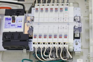
Examples of circuit breakers in distribution boards
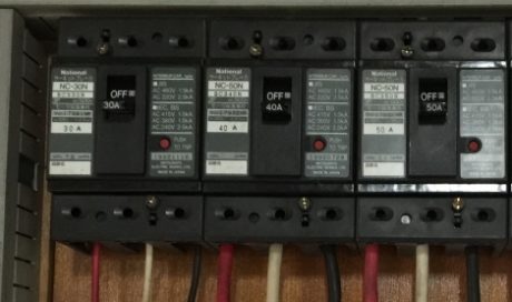
Safety breaker (wiring breaker)
It is a general circuit breaker like switchgear + fuse that can be used many times .
It is common to install instead of the switch.
There are the following concepts of selection.
Selection of Safety Breaker (Circuit Breaker)
· I want to prevent burnout of electric wire
· The withstand current capacity of the wire is lowered
· I want to recover earlier than fuse
operation time
Even if it exceeds the rated value (display value) it does not fall immediately (does not trip)
There are the following provisions.
| Rated current | Operating time | |
|---|---|---|
| 1.25 times the rated current | twice the rated current | |
| 30 A or less | 60 min or less | 2 min or less |
| 30 A – 50 A | 60 min or less | 4 min or less |
| 50 A ~ 100 A | 120 min or less | 6 min or less |
Even if the rated current is exceeded, it does not operate immediately.
Therefore, please select it taking into consideration the current to be used and the safety factor of the electric wire used.
Safety breaker is “switchgear + fuse that can be used many times”
About earth leakage breaker (Earth leakage circuit breaker)
The earth leakage breaker (earth leakage circuit breaker) is like “wiring breaker + ground fault monitor” .
Electric shock by earth fault (leakage) and function to prevent fire are attached.
To prevent electric shock from a ground fault (earth leakage), earth (ground) is common, but it is used in combination.
It is about the installation standard of earth leakage circuit breaker in case of Japan.
※ The contents of this section are approximate. Because there is possibility of revision,「電気設備の技術基準の解釈の解説」
Selection of earth leakage breaker (earth leakage breaker)
· Fire prohibited place such as pyrotechnic cabinet etc
· There is no mechanism for automatically shutting off when a ground fault is detected
· Place omitted for earth (ground)
As an exception
· Use the equipment at power stations, substations, etc.
· Use in a dry place
· Use it at 150 V or less in places other than moisture
· The equipment is covered with rubber, synthetic resin or other insulation
· Contact protective measures (measures not touched easily) have been done
· Earth (earth) resistance of C · D type grounding work is 3 Ω or less
The circuit is shut off by the current (sensitivity current) at the time of leakage.
As another method of classification, classify according to the operation time (time to shut off).
Type of sensitivity current
(Leakage current due to leakage current)
· High sensitivity type 30 mA or less
· Medium sensitivity type 1000 mA or less
Type of response speed (time until operation)
| type (shape) | operation time | corresponding function |
|---|---|---|
| High speed type | Within 0.1 s | Electric shock prevention |
| time delay | within 2 s | burnout prevention |
| Infinite time form | Within 0.3 s, depending on sensitivity current | Burnout prevention |
Sensitivity current of less than 15 mA, response speed less than 0.1 s is selected for earth leakage circuit breaker at earth omitted (300 V or less)
As a rough guide of the selection method in the function, it is as follows.
| Sensitivity current | Operating speed | Earth (ground) | Corresponding function |
|---|---|---|---|
| ~ 15 mA | Within 0.1 s | No ground, C / D type ground | Electric shock prevention |
| ~ 15 mA | Over 0.1 s | C · D grounding | Fire prevention |
| 16 mA to 500 mA | Within 0.1 s | C · D grounding | Electric shock prevention |
| 16 mA ~ 500 mA | 0.1 s over | C · D grounding | fire prevention |
| 501 mA ~ | Within 0.1 s | C / D grounding | Fire prevention |
| 501 mA ~ | 0.1 s over | C · D grounding | fire prevention |
There are standards for setting earth leakage breakers in Japan. It is necessary when monitoring earth faults.
About electromagnetic contactor and electromagnetic switch
Basically both are mainly used when connected to a motor or an electric heater.
It can control opening / closing of the circuit itself, also called magnetic switch from the feature.
The relationship between the electromagnetic contactor and the electromagnetic switch is as follows.
Electromagnetic switch = electromagnetic contactor + thermal relay
·thermal relay
Monitor the wire temperature to shut off the circuit by overload or short circuit.
electromagnetic contactor selection
· No load fluctuation
Selection of electromagnetic switch (electromagnetic contactor + thermal relay)
· Use a motor or an electric heater (there is load fluctuation)
· I want to shut down the circuit by overload or short circuit
(Monitor electric wire temperature)
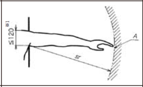
important point
· Setting of thermal relay
At the start of the motor, a large current (about 7 times the rating) flows for several seconds.
Depending on the setting, malfunction may occur at startup.
Let’s check the characteristic curve and adjust it at about 120% overload.
· Consideration of surge absorption
If you are using a large motor (large inductive load), the counter electromotive voltage will occur when opening the circuit.
This will markedly reduce the durability of the switch.
Therefore, it is necessary to suppress the counter electromotive force with a surge absorbing varistor or the like.
Especially when you want to control opening / closing of the circuit (remote)
Circuit protector
It is a circuit breaker made on the premise of protection of the control circuit of the electronic circuit and the load, load.
It becomes a circuit breaker whose operation until shutdown is fast.
Selection of circuit protector
· I want to block low capacity
· I also want to shut off the DC (DC) circuit
· Just a good rated current can not be found
(The rated current lineup is fine)
· I want to protect the secondary side wiring
Circuit breaker made on the premise of load protection
Household circuit breaker
Of course we also use circuit breakers in the home.
· Examples of distribution boards for household use (earth leakage circuit breaker, wiring breaker)
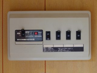
Normally, I think that the circuit breakers for households are configured as follows.
Ampere breaker (breaker with contract current value)
↓
Earth leakage circuit breaker (breaker with leakage test button)
↓
Circuit breaker (small breaker around)
I would like to explain how to deal with each breaker fault.
Anyone can recover if you cope without hurting.
Also, I have listed the possible factors, so please check as preventing recurrence.
If the ampere breaker has failed (tripped)
(Breaker with contract current value written)
Total electricity consumption in home exceeds contract value.
Let’s make the following correspondence.
2. Do not use devices that use large electric power at the same time
3. Stagger the timing of using devices that use large power
Power used exceeds contract value
If the earth leakage circuit breaker fails (trips)
(Breaker with leakage test button)
There is a possibility of electric leakage somewhere.
Try not to turn it on until you can check it.
If safety inside the house is confirmed, let’s correspond in the following order.
2. Turn on earth leakage circuit breaker
(At the time of a trip, the lever is temporarily stopped at the intermediate position, so OFF → ON once)
3. Turn on the circuit breaker one by one
4. When the earth leakage circuit breaker turns OFF again, check the corresponding position of the circuit breaker in the OFF state
There is a possibility that electric leakage is occurring somewhere
Circuit breaker failed (tripped)
It consumes a lot of electricity in part.
Usually, because the interrupter for wiring in the home is 15 A, if you use 3000 W under one circuit breaker it will fall within 2 minutes.
Let’s make the following correspondence.
2. Do not use large power at the same outlet, nearby outlet
3. If you really want to use a large amount of electricity, have an additional circuit created
Although it is not recommended, in the case of using for a short time, the following can be done due to the characteristics.
· Use slightly beyond 1500 W
· Use about 3000 W for about 1 minute